- Subscribe to RSS Feed
- Mark Topic as New
- Mark Topic as Read
- Float this Topic for Current User
- Bookmark
- Subscribe
- Mute
- Printer Friendly Page
Single Phase PLL
11-20-2013 10:45 PM
- Mark as New
- Bookmark
- Subscribe
- Mute
- Subscribe to RSS Feed
- Permalink
- Report to a Moderator
Is there any help file for single phase PLL? I found that VI. However, there is no any help or explanations about that.
- Tags:
- pll
11-21-2013 01:55 PM
- Mark as New
- Bookmark
- Subscribe
- Mute
- Subscribe to RSS Feed
- Permalink
- Report to a Moderator
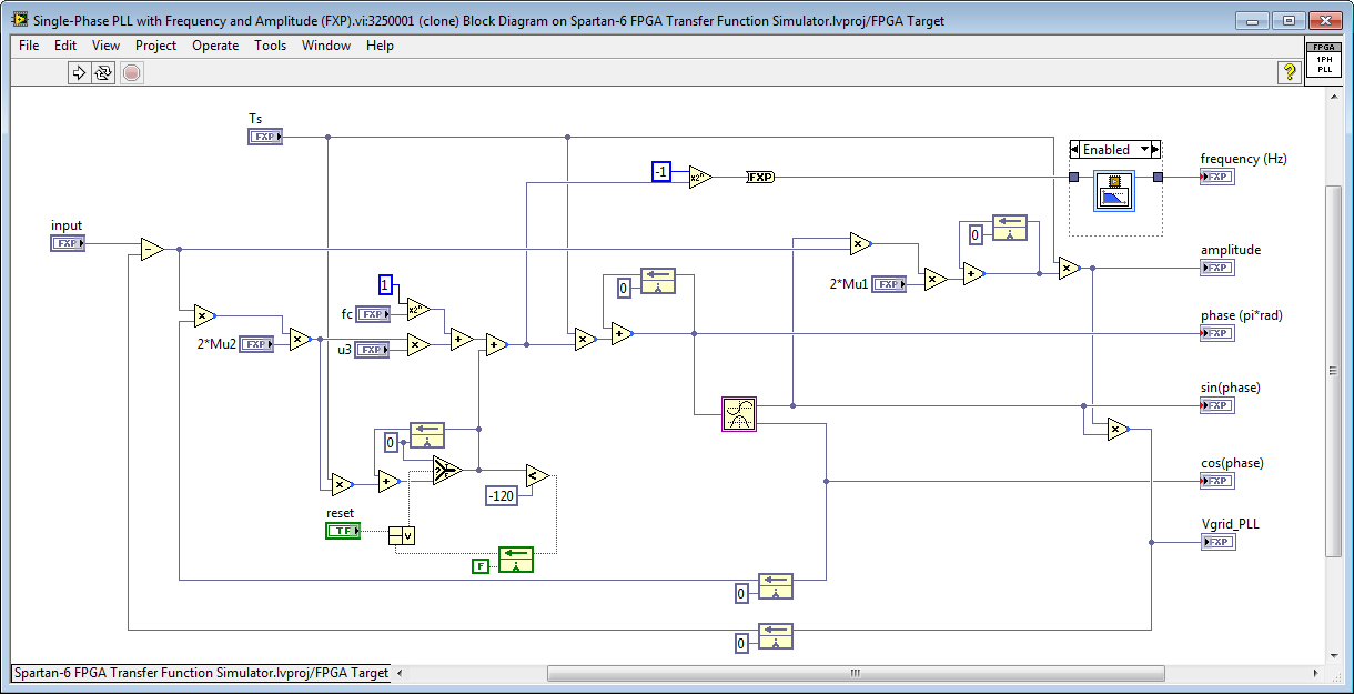
The single phase PLL IP was generously donated for use by the community by a power electronics team at a large company that's been using that particular PLL algorithm for many years with good results and is now developing power conversion applications based on the sbRIO GPIC. A nice feature of the IP core is that it provides amplitude information in addition to frequency and phase. Both fixed point and graphical floating point versions are available. However, the fixed point version has not been optimized to minimize resource utilization.
Since the IP core was donated, however, I don't think there is any documentation available. If you have specific questions, though, we can help answer them.
Here are screenshots and sbRIO-9606 General Purpose Inverter Controller benchmark information for the fixed-point and graphical floating point versions.
Fixed Point Version
- 946 slices (14%), 33 DSP cores (57%)
- Max 769 kHz execution speed
- Fixed point dynamic range
Graphical Floating-Point Point Version
- 2002 slices (29%), 5 DSP cores (9%)
- Max 268 kHz execution speed
- Floating point dynamic range
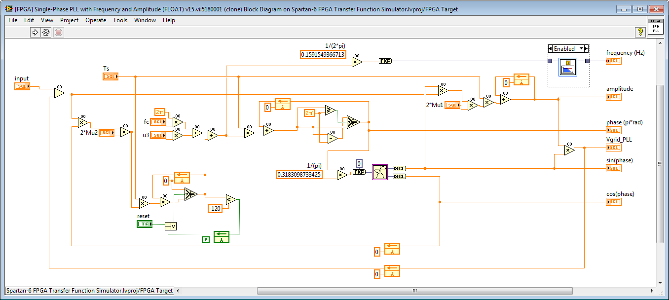
The floating point version is based on a new graphical floating-point palette for LabVIEW FPGA that I am planning to publish soon. If anyone wants early access before it is published, email me at brian.maccleery@ni.com.
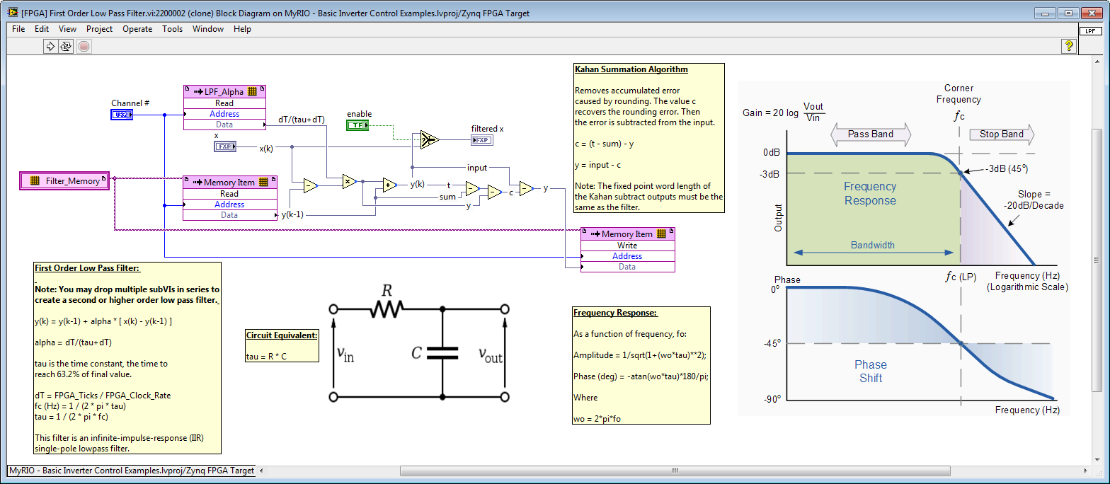
Note- To further reduce resource utilization in both versions, the butterworth filter could be replaced with the new First Order Lowpass Filter IP core shown below.
11-22-2013 01:21 AM
- Mark as New
- Bookmark
- Subscribe
- Mute
- Subscribe to RSS Feed
- Permalink
- Report to a Moderator
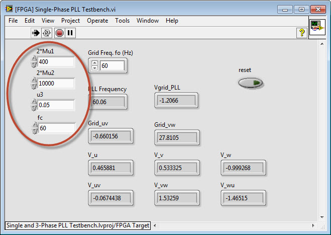
I wonder how to calculate the parameters such as 2*Mu1, 2*Mu2, u3 and fc. Thanks.
11-22-2013 06:47 PM
- Mark as New
- Bookmark
- Subscribe
- Mute
- Subscribe to RSS Feed
- Permalink
- Report to a Moderator
I'm not an expert on this particular PLL implementation, but here is my understanding.
Ts: Sampling time in seconds. Set this to match the rate of the loop containing the PLL.
fc: Reference frequency in Hz. Typically 50 or 60 Hz depending on your region.
Mu1: Amplitude tracking gain. Higher value gives faster tracking of amplitude changes.
Mu2: PLL gain. Higher value causes PLL to track frequencies farther from the reference frequency, fc.
u3: Phase detector gain. Higher value cause the PLL to eliminate phase error more aggressively.
Note that this depends on the PLL gain, Mu2.
Below are some nominal values that I recommend as a starting point if you need to track aggressively over a wide frequency range.

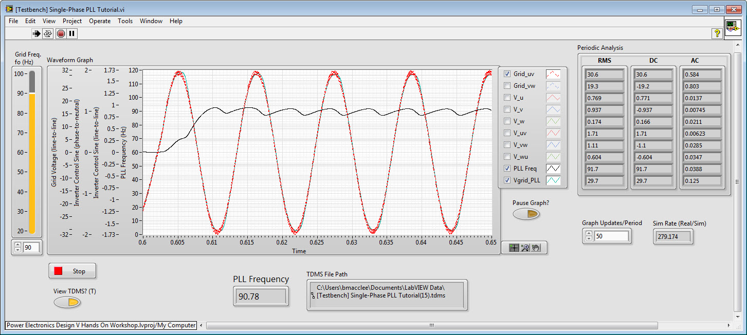
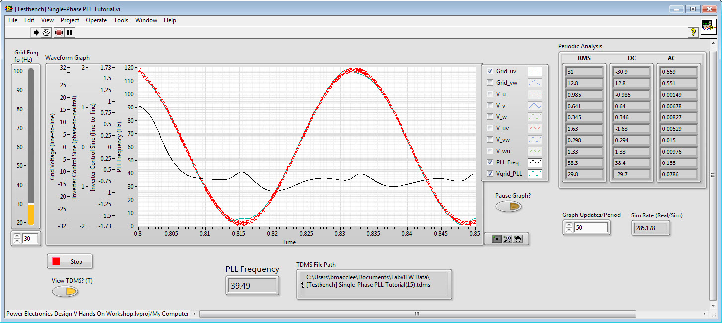
With those values, here are some simulation results using a noisy grid voltage waveform.
Startup Behavior:
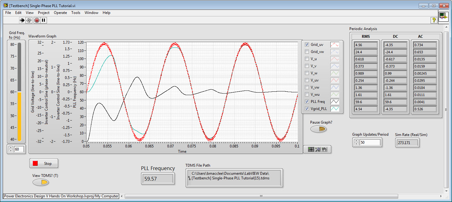
Jump from 60 to 90 Hz:
Jump from 90 to 30 Hz:
Here's how you would wire it up in a FPGA-based control application to produce 3 control sinewaves for a 3-phase sine-triangle PWM inverter:
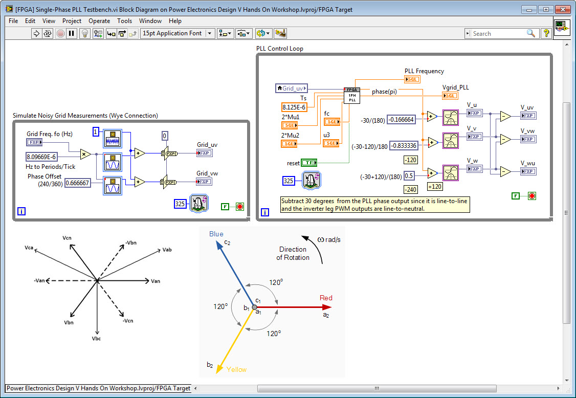
Note that for the screenshot above, I modified the phase output to make it compatible with the units of the 3-Phase PLL on the LabVIEW FPGA palette by wiring it to a different internal signal.
.jpg)
The simulation results are based on a modified version of the testbench application from the new inverter design V hands on workshop, as shown below.
![[Testbench] Single-Phase PLL.jpg](http://forums.ni.com/legacyfs/online/136976_[Testbench] Single-Phase PLL.jpg)
11-26-2013 10:49 PM
- Mark as New
- Bookmark
- Subscribe
- Mute
- Subscribe to RSS Feed
- Permalink
- Report to a Moderator
Thank you so much for your reply. It is very useful for me to choose the parameters of this vi.
12-09-2013 12:09 AM
- Mark as New
- Bookmark
- Subscribe
- Mute
- Subscribe to RSS Feed
- Permalink
- Report to a Moderator
Hi,
I am a NISH software engineer. I am very interested in the test bench you provided. Could you share the testbench and VI for single phase PLL? Thanks a lot.
12-09-2013 09:17 AM
- Mark as New
- Bookmark
- Subscribe
- Mute
- Subscribe to RSS Feed
- Permalink
- Report to a Moderator
Yes, where is the single phase PLL?
12-09-2013 10:06 AM
- Mark as New
- Bookmark
- Subscribe
- Mute
- Subscribe to RSS Feed
- Permalink
- Report to a Moderator
Here is the single phase PLL vi (fixed point). Please check it.
12-09-2013 12:07 PM
- Mark as New
- Bookmark
- Subscribe
- Mute
- Subscribe to RSS Feed
- Permalink
- Report to a Moderator
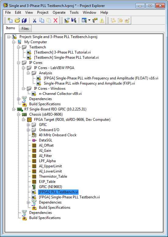
Here you can find a ZIP file containing a LabVIEW 2013 project with the single phase PLL IP cores (fixed point and floating point) as well as the testbench applications for each.
SingleAnd3-PhasePLLTestbenches.zip - Click here to download.
Instructions:
1. Unzip to a short directory path and navigate to the following LabVIEW Project file:
..\Single and 3-Phase PLL Testbench\Single and 3-Phase PLL Testbench.lvproj
2. Under My Computer, expand the Testbench virtual folder. Open [Testbench] 3-Phase PLL Tutorial.vi. Navigate to the block diagram and double-click the Desktop Execution Node to open the FPGA testbench VI. Run the top level application, [Testbench] 3-Phase PLL Tutorial.vi and try changing the Grid Freq. fo (Hz) and the PI gains while running the application. Click Stop when finished.
3. Under My Computer, expand the Testbench virtual folder. Open [Testbench] Single-Phase PLL Tutorial.vi. Navigate to the block diagram and double-click the Desktop Execution Node to open the FPGA testbench VI. Run the top level application, [Testbench] Single-Phase PLL Tutorial.vi and try changing the Grid Freq. fo (Hz). Navigate to front panel of the FPGA VI, [FPGA] Single-Phase PLL Testbench.vi, and try changing the single-phase PLL control settings, 2*Mu1, 2*Mu2, u3, and fc. See above in this thread for an explanation of those control settings.
Notes:
- The 3-Phase PLL IP core is not included in the ZIP file since that IP core is included with LabVIEW FPGA on the palette named FPGA Math & Analysis>Control.
- The [FPGA] First Order Low Pass Filter.vi IP core is also included in the Zip linked file above. This IP core uses less resources than the Butterworth low pass filter that's currently embedded in the single phase PLLs (both the float and fixed point versions). Consider replacing the Butterworth filter IP core with the first order low pass filter IP core. Also, a floating point version of the first order low pass filter IP core could easily be created-- in this case the Kahan Summation Algorithm portion of the algorithm is not needed since rounding errors would be insignificant for a floating point first order filter algorithm.
12-10-2013 07:37 PM
- Mark as New
- Bookmark
- Subscribe
- Mute
- Subscribe to RSS Feed
- Permalink
- Report to a Moderator
Thanks a lot!
I focus on the measurement of electrical power signal. This is very helpful for me and bring some more new ideas for signal processing!
