- Subscribe to RSS Feed
- Mark Topic as New
- Mark Topic as Read
- Float this Topic for Current User
- Bookmark
- Subscribe
- Mute
- Printer Friendly Page
SPI for Shif-Register (74HC595)
12-14-2013 04:13 PM
- Mark as New
- Bookmark
- Subscribe
- Mute
- Subscribe to RSS Feed
- Permalink
- Report to a Moderator
Hi!
I'm starting to work with the SPI communication of the LIFA Toolkit —I'm already worked with this communication in the arduino software with good results— and the Shif-Register 74HC595, but my problem is that I don't know how select which arduino pin will be for the pin 11 (SH_CP Clock) and pin 14 (DS Serial Input) of the 74HC595. I'm only using one 74HC595. For the Pin 12 (Latch) I'm using a Digital Output in my LabVIEW program.
I started my code based in some discussions, and this is what I got :
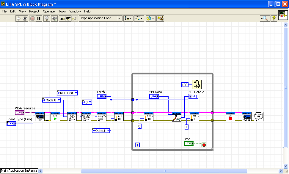
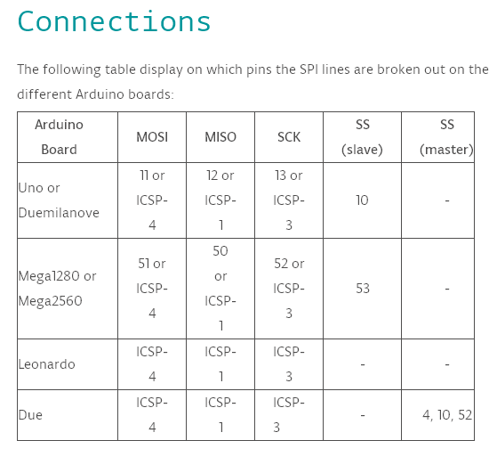
When I worked with this in the arduino software each pin must be configured: Latch, Clock and Serial Input. But from some search that I made about the ISP, I conclude that in this case I don't need set each pin, if not I must use the "Chip Select DIO Pin" but, for more that I try to understanding how it works, I don't get it. I found the following table of the SPI connections for the Arduino UNO, but I still don't know how create the connection between my Arduino UNO and the 74HC595 using the SDI/SDO convention.
Please help me. Thanks.
12-14-2013 05:11 PM
- Mark as New
- Bookmark
- Subscribe
- Mute
- Subscribe to RSS Feed
- Permalink
- Report to a Moderator
Form what I understand about your question it looks like you should use the following pins with the Arduino Uno.
Pin 11 MOSI for the data byte being sent to the 74HC595
Pin 13 SCK for the clock signal for the 74HC595
Use any convenient Arduino pin for a Latch pin for the 74HC595
hrh1818
12-14-2013 05:37 PM
- Mark as New
- Bookmark
- Subscribe
- Mute
- Subscribe to RSS Feed
- Permalink
- Report to a Moderator
Ok, then the pin 11 (MOSI) will be connected to the pin 14 (Serial Input) of the 74HC595, and the pin 13 (SCK) to the pin 11 (SH_Cp Clock) of the 74HC595. But one more cuestion: what arduino pin do I need choose for the "Chip Select DIO Pin" input of the "SPI Send Receive" block?
Thanks.
Edit:
I left the "Chip Select DIO Pin" without connection, and I run the program and it's working! Now my cuestion is: what is the function of the "Chip Select DIO Pin"?
12-14-2013 06:18 PM
- Mark as New
- Bookmark
- Subscribe
- Mute
- Subscribe to RSS Feed
- Permalink
- Report to a Moderator
The Chip Select DIO Pin terminal does exactly what you are doing with the Latch pin. So, you can remove the digital write pin subVIs before and after the SPI Send/Receive subVI and simply wire the Latch pin number to that terminal. It will make your program a little more efficient and less cluttered.
12-14-2013 06:33 PM
- Mark as New
- Bookmark
- Subscribe
- Mute
- Subscribe to RSS Feed
- Permalink
- Report to a Moderator
Thanks to both for the help, now I understand and my program is working very well.
08-15-2015 09:33 AM
- Mark as New
- Bookmark
- Subscribe
- Mute
- Subscribe to RSS Feed
- Permalink
- Report to a Moderator
03-24-2024 12:17 PM
- Mark as New
- Bookmark
- Subscribe
- Mute
- Subscribe to RSS Feed
- Permalink
- Report to a Moderator
Hi I'm working on a very similar project as one of my projects. Would you mind sharing the final VI in order to see how to do it properly?
Thanks in advance.
