From 04:00 PM CDT – 08:00 PM CDT (09:00 PM UTC – 01:00 AM UTC) Tuesday, April 16, ni.com will undergo system upgrades that may result in temporary service interruption.
We appreciate your patience as we improve our online experience.
From 04:00 PM CDT – 08:00 PM CDT (09:00 PM UTC – 01:00 AM UTC) Tuesday, April 16, ni.com will undergo system upgrades that may result in temporary service interruption.
We appreciate your patience as we improve our online experience.
03-27-2014 09:14 PM
Hardware-in-the-loop Testing Requirements:
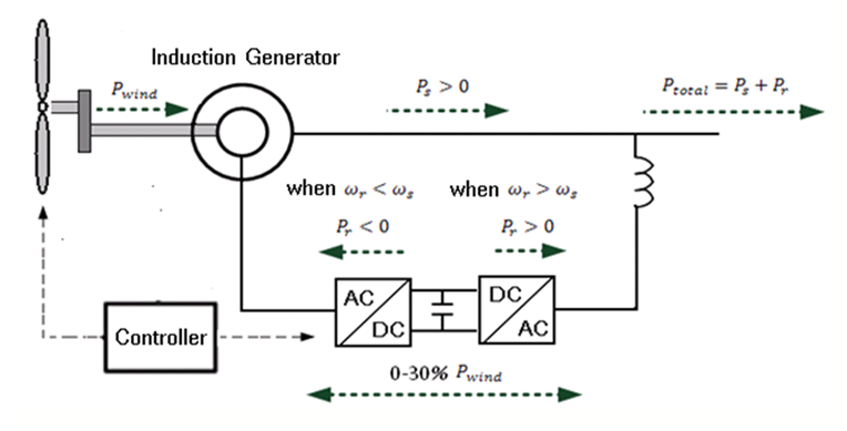
There has been a growing interest in the use of wind energy as environmental concerns are on the rise. The advantage of the doubly-fed induction generator (DFIG) system is that its back-to-back PWM converter only flows through part of the wind turbine energy. This could lower the cost of the power electronics components. By controlling this back-to-back PWM converter, the frequency and amplitude of the rotor voltage can be regulated to realize a variable speed constant frequency operation and the maximum wind power tracking.
For the high-power system like the doubly-fed induction generator, it is inconvenient to directly perform the experiment on the physical device. So the end users would like to have a real-time simulator for developing and testing the DFIG converter controller.
Technical Challenges:
Doubly-fed induction generator is a typical power electronics system, unlike the traditional AC power system; power electronics system contains fast switching devices, the normal simulation method requires very small step size, usually several microseconds, to achieve accurately simulation results. However, normal CPU-based real-time hardware system is not able to support such small step size.
For the doubly-fed wind turbine system itself, the model of no-load mode and the model of grid-tied mode are different; most of the simulation software does not support the no-load excitation mode simulation.
FPGA and Averaged Method–based Real-Time Simulation
One way to achieve the power electronics system real-time simulation is to leverage FPGA and the averaged method [Reference 1]. There are two key points of this method. One is that using FPGA to measure the PWM Pulses, the other is using equivalent circuits to replace original converter bridges. StarSim Real-Time Module contains necessary models and functions to support FPGA and average method based power electronics system real time simulation.
The doubly-fed induction generator provided by StarSim considers the no-load mode, and supports the smooth transition from the no-load mode to grid-tied mode.
DFIG Hardware-in-the-loop Testing Solution
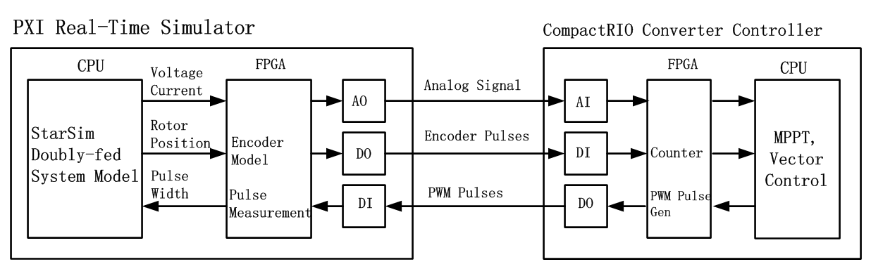
This solution consists of two parts. One is CompactRIO-based converter controller; the other is PXI-based doubly-fed wind turbine real-time simulator. The two systems are connected with I/O boards, and the interface between them is as same as the interface between the controller and the true physical system, i.e., the controller acquires the current and voltage signal, also the encoder pulses from the simulator (or the true physical plant); and sends out the PWM Pulses to control the back-to-back converter.
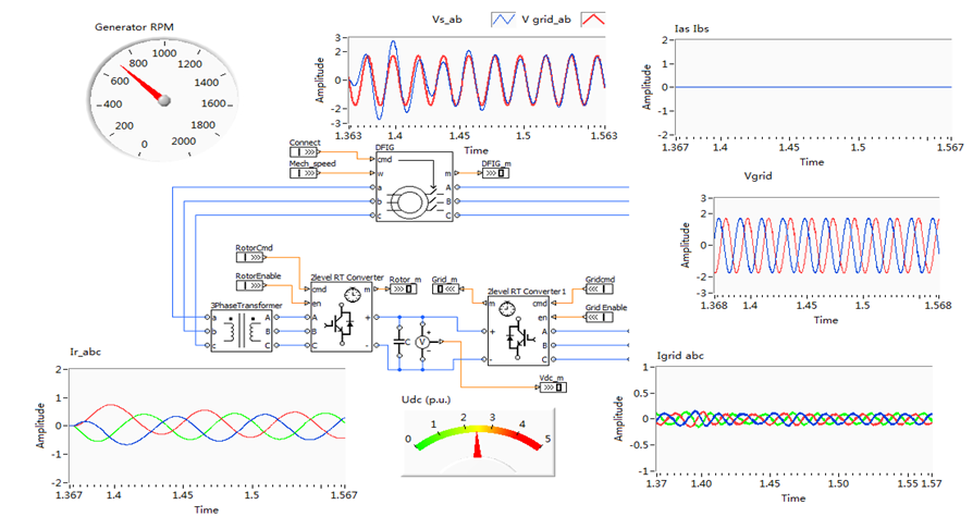
The below figure shows the graphical interface of the real-time simulation system. The generator is in the no-load mode. The converter controller is controlling the excitation (rotor) current of generator to let the generator be ready for the grid-tied mode, i.e., the frequency, the amplitude and the phase of the stator voltage are as same as those the grid voltage. The waveform graph above the DFIG generator shows both the stator voltage (blue) and the grid voltage (red). The process of regulation can be clearly observed.
The below figure is the lab photo of the doubly-fed wind turbine HIL system. It shows the PXI-based real-time simulator and the CompactRIO-based Converter Controller.

References:
[1] Lian K.L., Lehn P.W., Real-time simulation of voltage source converters based on time average method
Kevin.Wang | kevin.wang@modeling-tech.com
Business Development Manager
ModelingTech Energy Technology Co.,Ltd
Copyright © 2013 ModelingTech Energy Technology Co., Ltd
