From 04:00 PM CDT – 08:00 PM CDT (09:00 PM UTC – 01:00 AM UTC) Tuesday, April 16, ni.com will undergo system upgrades that may result in temporary service interruption.
We appreciate your patience as we improve our online experience.
From 04:00 PM CDT – 08:00 PM CDT (09:00 PM UTC – 01:00 AM UTC) Tuesday, April 16, ni.com will undergo system upgrades that may result in temporary service interruption.
We appreciate your patience as we improve our online experience.
04-04-2014 04:08 PM
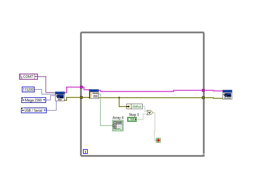
Hello i´m new in arduino and i´ve a problem to create a custom firmware for LIFA and Vi in labview to read all ports beacause a i need monitoring 50 relay when they are turn on. as you can see in my vI and Lifa i wrote a case with this action but i only recives 16 inputs, i hope you can help me.
case 0x37: // Digital Read Port
retVal = 0x0000;
for(int i=0; i <=53; i++)
{
if(digitalRead(i))
{
retVal += (1<<i);
}
}
Serial.write( (retVal & 0xFF));
Serial.write( (retVal >> 8));
break;
04-04-2014 06:41 PM
About your code. You are only sending back two bytes meaning you will only get 16 bits of information. Also, I don't think you will be able to get all of the bits into an integer. Based on the documention, an int is only two bytes and a long is 4 bytes (32 bits). Therefore, you will need to either break it up into four int's or two long's. Then, you need to make sure that you send back all 8 bytes to LabVIEW.
Just as a reference, I wrote a VI with custom firmware to write to all digital pins here.
04-08-2014 11:49 AM
Ok i followed you advice and i did something like this:
| case 0x37: | // Digital Read Port |
| retVal = 0x0000; | |
| for(long i=0; i <=32; i++) | |
| { | |
| if(digitalRead(i)) | |
| { | |
| retVal += (1<<i); | |
| } | |
| } | |
| Serial.write( (retVal & 0xFF)); | |
| Serial.write( (retVal >> 8)); |
retVal = 0x0000;
| for(long i=32; i <=53; i++) | ||
| { | ||
| if(digitalRead(i)) | ||
| { | ||
| retVal += (1<<i); | ||
| } | ||
| } | ||
| Serial.write( (retVal & 0xFF)); | ||
| Serial.write( (retVal >> 8)); | ||
| break; |
and i try to customize my vi but i didn't progress. it only reads 16 bites
04-08-2014 02:28 PM
retVal is only an int, not a long, therefore you cannot use it to store 32 bits. If you want to use retVal, you need to do 16 bits at a time. You would send 2 bytes back to LabVIEW at a time (repeating a total of 3 times) and then you would need to do another byte to get the final 6 digital pins. This will be a total of 7 bytes sent to LabVIEW.
04-08-2014 08:19 PM
Well i did the customize but in the VI y can't see all booleans any advice whit this problem?
04-09-2014 01:06 AM
I see two things wrong with the Arduino-side code. Your start and end points for your loops are not quite correct. The first loop is correct but all subsequent loops are not. Also, when you shift the bit, you are shifting by 16, 17, 18, etc in the loops where your i does not start at zero. You will need to compensate to make sure that the bit shift is only in the range of 0 and 15.
This is how I would do the for loop limits:
for(int i = 0; i < 16; i++)
for(int i = 16; i < 32; i++)
for(int i = 32; i < 48; i++)
for(int i = 48; i < 54; i++)
05-29-2015 05:03 PM
hi!!
i have a similar problemm like you. how did you solve it?
i need your help!!!!
thank!!!
05-29-2015 05:49 PM
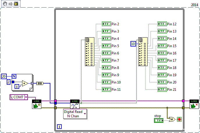
You should switch to LINX, you can ready as many pins as you want with a single VI (Digital Read N Chans.vi).
Also, FYI, the Arduino Mega only works with a 9600 baudrate.
05-31-2015 03:21 PM
thank Nathan_B.
I have used Linx, and all ok, but i have had to used Digital Read 1 Chans.vi, because i dont´know or i can´t configured the arrays to output to used digital read N chans like you say to me.
but a lot of thank .

05-31-2015 04:18 PM
I'd highly recomend that you take a look at some basic LabVIEW training documents/websites. You could probably search for information specfically about arrays in LabVIEW.
One way to do it is like this:
For further questions regarding LINX, you should post on the forums at http://www.labviewmakerhub.com/
Also, make sure you take a look at this information regarding LINX and how to properly use LINX VIs.
P.S. If you have LabVIEW 2014 or later, you can save the above image to your computer and then drag and drop it onto the block diagram of an empty VI.
