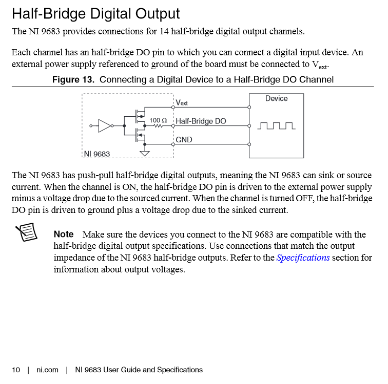
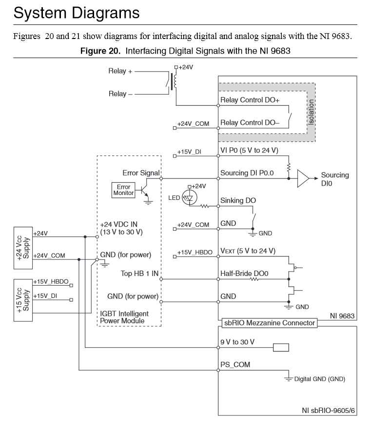
Yes, see the NI 9683 GPIC User Guide and Specifications. Most likely you didn't connect a 5-30 VDC supply to Vext terminal (external power supply) on the Half-Bridge Digital Outputs. Note that these outputs are gate command signals rather than gate drive signals. They are push-pull digital outputs designed for gate driver boards such as CT Concept, AgileSwitch, Semikron SKiiP3/SKiiP4, etc. An external supply input is used to provide flexibility in the digital output level and slew rate (5 V level is faster than 15 V level at the other end of a ribbon cable due to the output driver slew rate and cable/load capacitance.) Also note that the output impedance of the half bridge digital outputs is 100 Ohms to match typical ribbon cable impedance. The maximum cable length depends on the signal integrity of the gate driver board you are connecting to. Worst case is the SKiiP3 product- maximum cable length to SKiiP3 is 1 meter.
In the user manual, see especially pages, 10, 15-16, 19-20...