- Subscribe to RSS Feed
- Mark Topic as New
- Mark Topic as Read
- Float this Topic for Current User
- Bookmark
- Subscribe
- Mute
- Printer Friendly Page
NI MyRIO Electrical Engineering Learning Board (VOLUNTEER REQUESTED)
08-07-2014 10:02 AM
- Mark as New
- Bookmark
- Subscribe
- Mute
- Subscribe to RSS Feed
- Permalink
- Report to a Moderator
Vision Statement
- Goal is to make learning circuits, power electronics and electric machines more fun, make a product inexpensive enough for students to own, replace prohibitively expensive rapid control prototyping (RCP) systems, multichannel scopes and logic analyzers, and enable students to learn in simulation and experimental contexts and go back and forth in a mouse click.
Learning Objectives
- Support experiential learning using NI MyRIO from introductory electrical circuits and RLC filters, motors/generators, solar and wind energy, electric vehicles, power generation / transmission, power quality analysis and reactive power compensation, microgrids, battery storage, DC-to-DC and DC-to-AC power electronics circuits, single and 3-phase power converters to advanced power electronics.
Executive Summary
- All experiments can be conducted at home without physical hardware using pre-built Multisim co-simulation models and custom LabVIEW user interfaces optimized for focused, interactive learning of the target learning objectives
- Safe to touch voltages with 9 channels of built in instrumentation (50 kS/s)
- Direct control of MotorSolver motors and dyno kits
- Gate drivers and voltage/current sensing for external bread board circuits (i.e. discrete RLC circuits, MOSFETs/IGBTs, etc.)
- Grid sensing, synchronization and power quality analysis using external stepdown AC wall transformer ($10)
- Support for real-time HIL experiments with simulator compatible inputs/outputs
- IGBT module can be replaced without soldering ($20)
- Open source schematic and layout
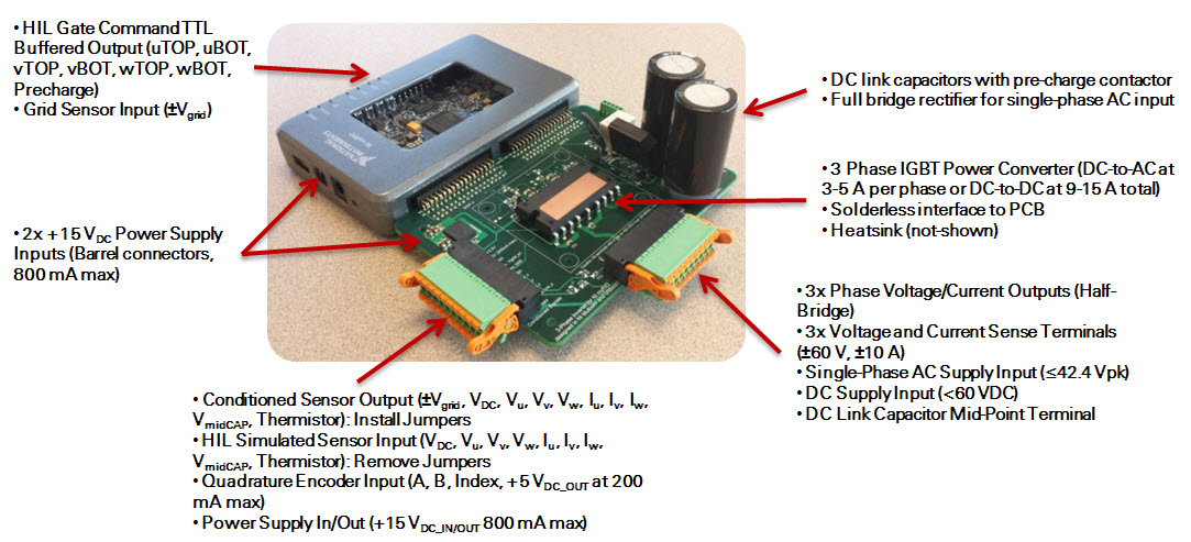

Technical Specifications
- Designed for “safe to touch” voltage level experiments with 9-channel voltage and current instrumentation (50 kS/s) including 3 voltage and current sensing inputs
- Fully integrated NI Multisim co-simulation tools with a range of electrical circuit models for point-by-point student interaction with simulated circuits using LabVIEW graphical user interface, automatic transition to experimentation, and built-in experimental vs. simulation charting and file logging
- Pre-built model based control design & simulation software with interactive configurable control settings, live scope display, power quality analysis and phasor diagrams
- Live waveform graphing and data logging in TDMS format for post-processing analysis via Microsoft Excel, The MathWorks, Inc. MATLAB®, NI DIAdem, and NI LabVIEW
- Timestamped data recording for effortless waveform chart comparison of simulated versus experimental results for both desktop co-simulation and real-time HIL simulation
- Built-in sensors for voltage and current (x3), DCLink, DCLink midpoint, grid voltage (from external step-down transformer), and IGBT thermistor temperature sensing
- 3 push/pull gate driver circuits for external bread boarding of discrete MOSFETs/IGBTs circuits
- 3 half-bridge DC-to-AC inverters / DC-to-DC converters for direct control of single or 3-phase loads such as MotorSolver
- Quadrature encoder inputs for motor position and speed sensing with + 5 VDC supply output
- 3 extended range sensing inputs for probing voltage and current anywhere in an external circuit
- Full bridge passive rectifier for powering DC link capacitors via AC wall transformer and built-in DC Link capacitors with pre-charge contactor for inrush protection
- DC Link can be powered using a DC power supply, solar panels or batteries
- Supports grid phase lock loop (PLL) experiments when fully bridge rectifier is powered from low cost external 24 VAC wall transformer (U.S. MGT-2450P, Europe/Asia 77DA-40-24)
- IGBT inverter half-bridges rated at ~5 A continuous, 10 A peak, ≤42.4 Vpk or <60 VDC with built-in heat sink (* Continuous current rating to be determined)
- Support for hardware-in-the-loop experiments (HIL) via buffered gate command signal outputs and compatible simulated sensor feedback inputs
- Socketed IGBT intelligent power module
- Hand solderable, open-source circuit design and layout can be modified by students for capstone design projects
- Flexible Half-Bridge IGBT Output Configurations:
- When powered by a single AC or DC power supply, three IGBT half-bridge circuits provide unipolar half-bridge outputs: +VDC or PGND
- When powered by two floating DC power supplies, three IGBT half-bridge circuits provide bipolar half-bridge outputs: +VDC/2 or -VDC/2
- When powered by a single AC or DC power supply, three IGBT half-bridge circuits provide unipolar half-bridge outputs: +VDC or PGND
Circuit Schematic

Curriculum
• Supports experiential learning from introductory electrical circuits to RLC filters, motors/generators, solar and wind energy, electric vehicles, power generation/transmission, reactive power compensation, microgrids, battery storage, DC-to-DC and DC-to-AC power electronics circuits, single and 3-phase power converters, and advanced power electronics
• All experiments can be conducted at home without physical hardware using accurate time-adaptive co-simulation tools based on NI Multisim and NI LabVIEW FPGA. High level control algorithms are easily switched from simulation to deployment mode, with chart comparison of experimental versus measured results (see below).
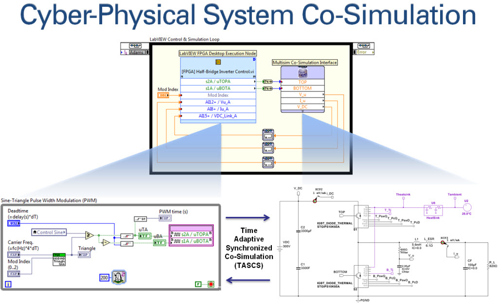
Comparing Simulated versus Measured Results

• Pre-built LabVIEW control experiments range from simple open loop 3-phase power generation and analysis to advanced control design (see below)
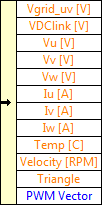
FPGA Interface Cluster:
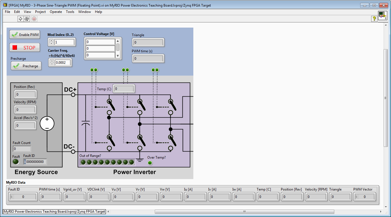
FPGA Front Panel with Animated Transistors:
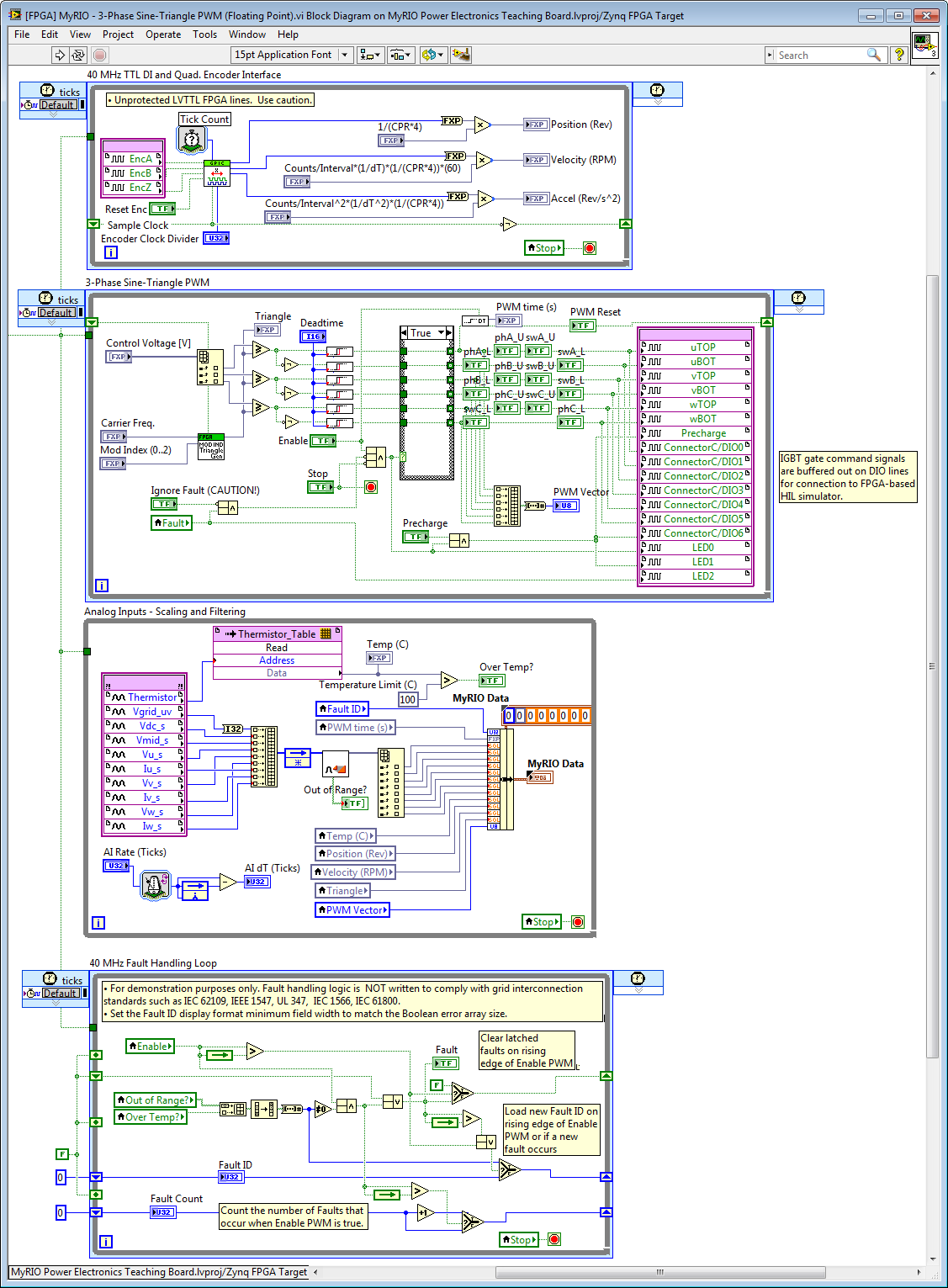
Graphically Programmed FPGA Control, Sensing & Protection Loops (FPGA Block Diagram):
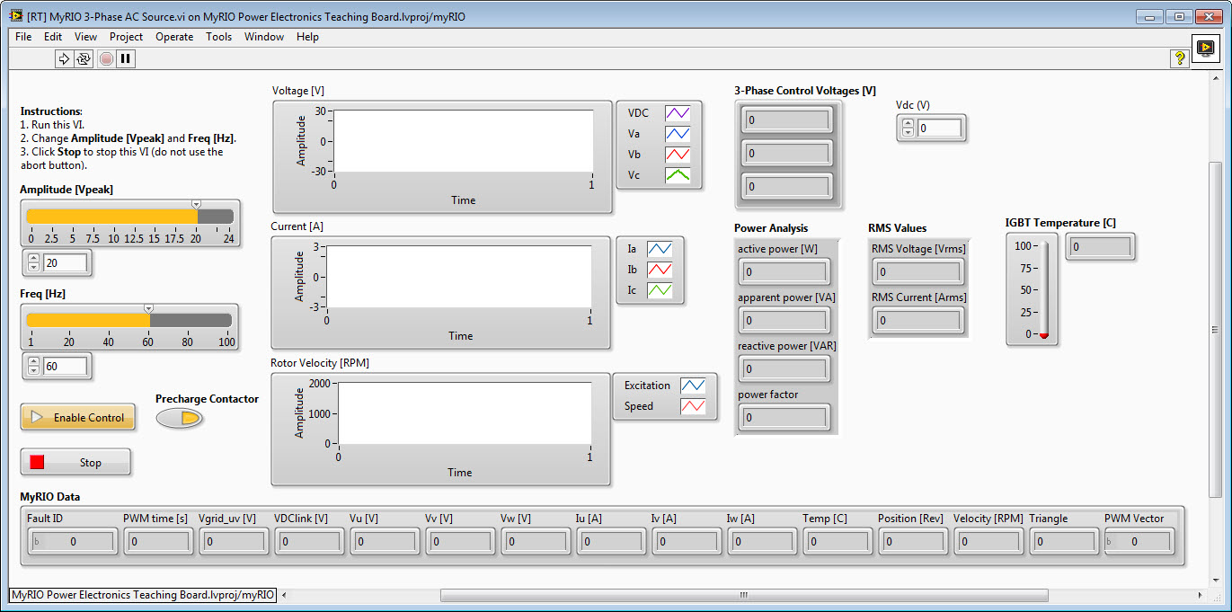
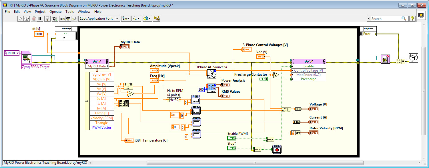
3-Phase AC Power Source and Power Analysis Experiment
3-Phase Source Signal Generator Subsystem (control signals for sine-triangle PWM):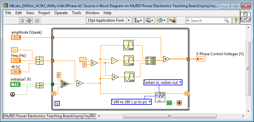
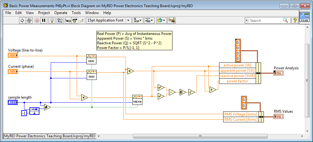
Power Analyzer Digital Signal Processing Subsystem:
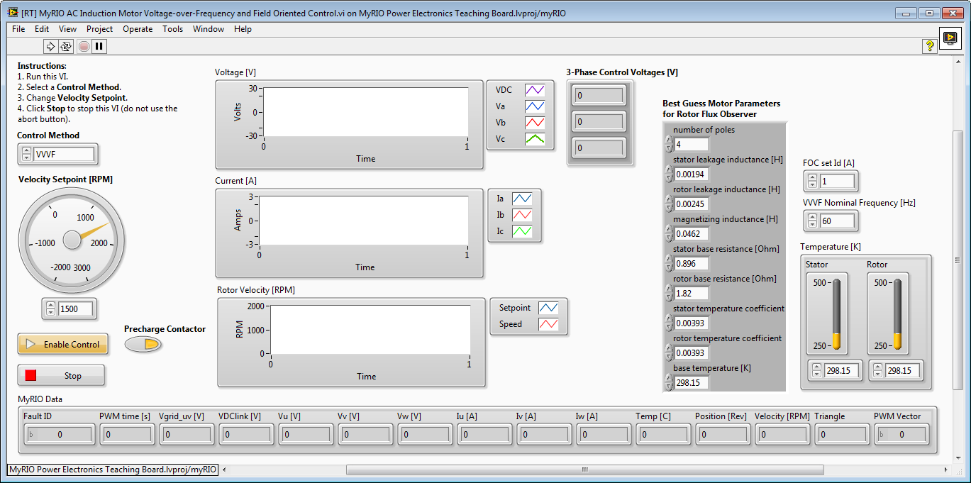
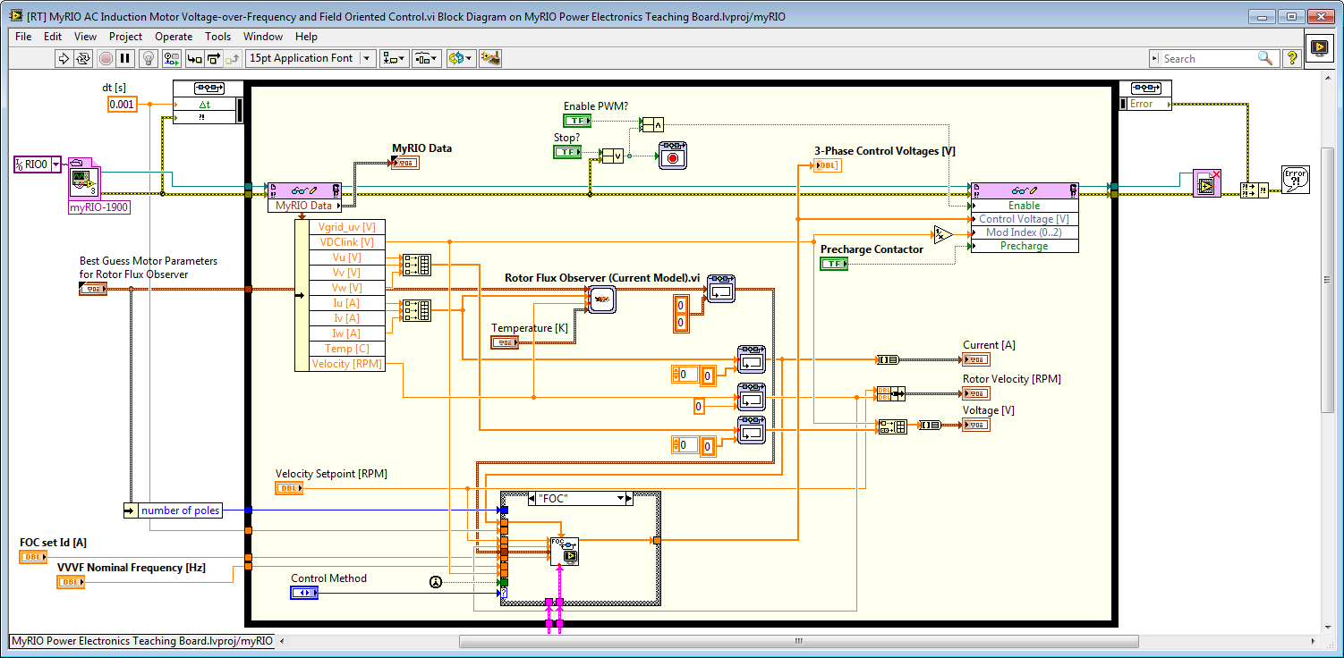
3-Phase AC Induction Motor Voltage-over-Frequency and Field Oriented Control
AC Induction Motor Field Oriented Control (FOC) Algorithm Subsystem:
 Algorithm.png)
PI Controller Subsystem:

dq-to-alpha/beta (Inverse Park Transform) Subsystem:
.png)
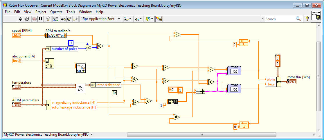
ACIM Rotor Flux Observer Subsystem (located at top level control):
FEEDBACK REQUESTED!
PLEASE EMAIL BRIAN.MACCLEERY@NI.COM
10-02-2014 01:29 PM
- Mark as New
- Bookmark
- Subscribe
- Mute
- Subscribe to RSS Feed
- Permalink
- Report to a Moderator
Status Update;
- We have allocated R&D resources to make the MyRIO EEEL board (Electrical Engineering Experiential Learning) an official product, with the goal of making it robust and very cost effective.
- If you are interested and able in the near future to begin developing curriculum (elementary, high-school, undergrad or graduate level) or STEM-oriented demonstrations focused on attracting young folks to a career in engineering, please let us know as soon as possible. We are seeking lead users for a small early access / beta program.
10-02-2014 02:14 PM
- Mark as New
- Bookmark
- Subscribe
- Mute
- Subscribe to RSS Feed
- Permalink
- Report to a Moderator
Nice developments Brian, congrats.
We have a few MyRIOs coupled to electromichanical setups, and in fact have been planning to connect the device to power converters. The first thought was more about a class D amplifier rather than a 3phase inverter, however.
What is your impression with using multiplexed ADCs on MyRIO in the power conversion applications, where one would probably prefer simultaneous sampling? I've been plannign to use MyRIO on a higher speed buck-boost (200kHz sampling), but expect havy oscilations and offsets (not using integral action at this moment) due to the offset measurement instances and delays.
I am very much currious about the board, would you be able to provide a more detailed board schematics than the one in the figure? My particular interest is whether you provide any currrent and voltage measurements out of the box.
And the last question: I've noticed that the control functionality is implemented completely on the processor. Did you try to run it faster than 1kHz? That would require moving from control design and simulation loop to a timed loop of course. Currently we have the controller for the electromechanical system running at 10kHz in the FPGA because we weren't able to make it run reliably on the processor faster than 3kHz.
10-11-2014 12:26 PM
- Mark as New
- Bookmark
- Subscribe
- Mute
- Subscribe to RSS Feed
- Permalink
- Report to a Moderator
Sorry for the slow reply. The latest Multisim schematic draft is attached. Here's a screenshot.
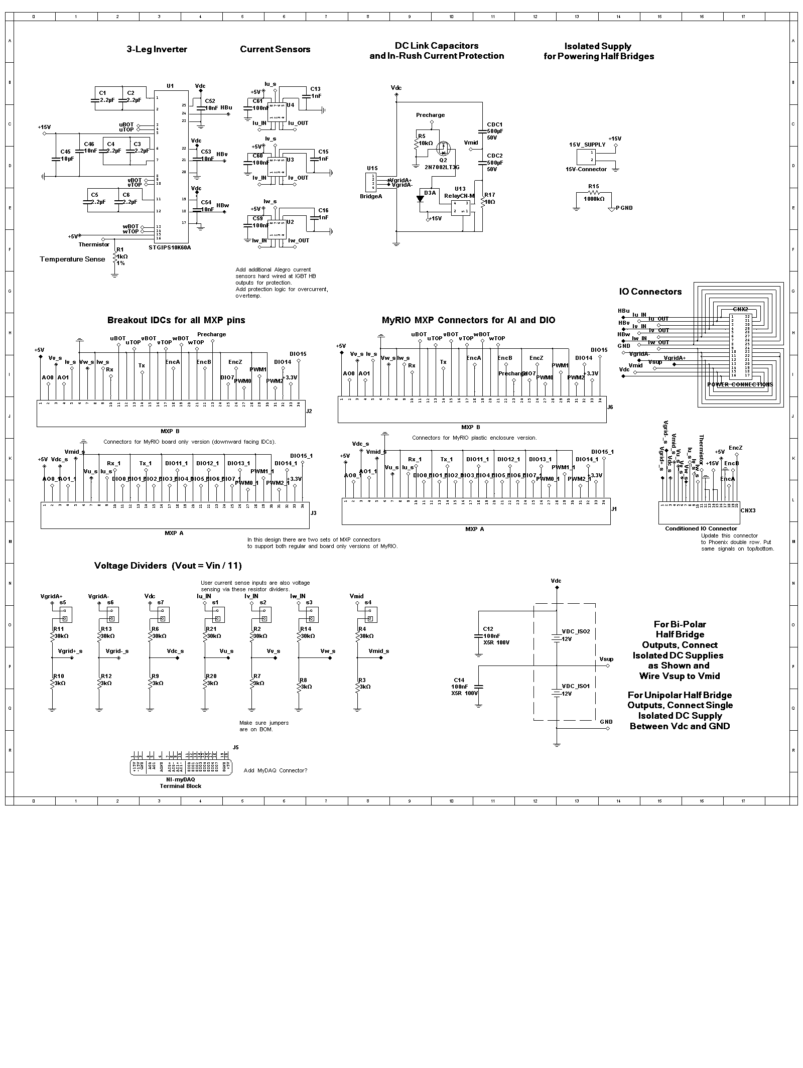
Updates we're working on (not reflected in attached schematic):
1. Dedicated over-current and over-temperature protection circuitry using comparators built into the circuit board. This eliminates dependence on FPGA-based protection logic for reliability reasons, and ease of programming. This means adding dedicated current sensors in the IGBT half-bridge output legs. There will be three additional current sensors (with voltage sense dividers) that can be used for sensing current anywhere in the external circuitry (as shown in the attached schematic).
2. We are considering adding a linear current supply (1 A) and linear voltage supply (perhaps LM317 type) controlled by MyRIO analog outputs. This would provide the ability to provide clean linear sources for circuit experiments (on an external breadboard), such as measuring the Bode plot response of RLC circuits and I-V transfer characteristics of MOSFETS/DIODES/IGBTs. (See Ed Doering's introductory electric circuits and microelectronics curriculum based on NI myDAQ that goes with Circuits textbook by Fawwaz T. Ulaby of the University of Michigan and Michel M. Maharbiz of the University of California, Berkeley.)
Thanks for the thoughts on the multiplexed analog inputs and real-time control loop performance. Those are both valid concerns on our radar. The thinking is that for an academic learning type product, keeping the price down is critical and the goal in most cases will be to program the control loops in the LabVIEW Control Design & Simulation (CD&Sim) Loop on one of the real-time processors. That provides a rapid control prototyping (RCP) type simulation modeling type programming experience, traditionally associated with expensive high end products from specialty RCP/HIL companies. However, we could deliver that type of simulation loop type programming experience at a very low price-- however at lower speeds.
On MyRIO the control loop rates in LabVIEW Real-Time will most likely be limited to around 1 kHz. The thinking is that for academic learning purposes, many closed loop control experiments can be designed with that limitation in mind. (Limit the gain crossover frequency of the plant to around 100 Hz). Meanwhile, for higher bandwidth power electronics experiments, the pulse width modulation and some of the PID control loops can run in the FPGA with the setpoints updated by the real-time processor. For example, in a cascaded control loop experiment, the inner current control loop could run at 10 kHz in the FPGA, sine-triangle PWM could run at 2 MHz in the FPGA, and the slower outer loops (say velocity and position) can be executed in the real-time processor with the simulation loop type programming experience. At the same time, triggered data captures could be acquired and graphed at 10 kHz. The goal in most cases would be to use a fixed FPGA personality and have the students spend their time in the high level CD&Sim environment.
Your use case for a high speed buck-boost converter with 200 kHz sampling would most likely be outside the scope of this product. The MyRIO analog inputs do have a 500 kHz aggregate sampling rate, so I suppose you could sample two channels at 250 kHz. However, the current sensor bandwidth will most likely be set around 40 kHz to enhance the accuracy and reduce noise. I'd recommend CompactRIO or PXI R Series boards for a high speed application like that. The main focus of the MyRIO system would be high school and undergraduate level learning.
Regarding the multiplexed nature of the analog to digital converter on MyRIO, the thinking is that for most lower speed academic experiments it may not be a problem. On a commercial power electronics control product you would certainly want simultaneous sampling. Do you think it's an issue for undergraduate type power electronics experiments? If so, we could add shift registers to the FPGA application to remove the phase shift caused by the ADC multiplexer. That's pretty inexpensive in terms of FPGA resources.
Let us know your thoughts. Is 1 kHz control loops an acceptable limit for most undergraduate experiments, with a some high speed PID channels available in the FPGA (with the ability to select which channel goes to the input and which goes to the output), and MHz speed sine-triangle pulse width modulation also performed in the FPGA?
Thanks for your help!
10-15-2014 06:22 AM
- Mark as New
- Bookmark
- Subscribe
- Mute
- Subscribe to RSS Feed
- Permalink
- Report to a Moderator
Brian,
Thanks for the extensive reply. My use case is outside the scope of MyRIO platform of course. I tried to mitigate the multiplexing issue by pipelining the ADC operation and scheduling multiple observers to predict the missing samples. In theory it works ok, but in practice there can be some oscillations still.
1kHz should be more or less ok for AC motors (or grid interfacing), but for the BLDCs one may need to embed some functionality into the FPGA.
We use MyRIO with some electromechanical setups with the resonance frequency ~60Hz and running the controller with less than 1kHz can be undesirable as the controller gain has to be very low and the system response is very sluggish. To truly feel the stiffness generated by the control system in the mechanical part we've had to run the controller in the FPGA with 10kHz sampling rate.
How fast are you expecting to finalize the design and make it available to the public? I would be tempted to use it for a case stude in the Model Predictive Control course (MSc. level) in about 5 months time.
Regards,
Veaceslav
01-19-2015 10:02 AM
- Mark as New
- Bookmark
- Subscribe
- Mute
- Subscribe to RSS Feed
- Permalink
- Report to a Moderator
Hi Brian,
Are there any news on the board? I am still interested in using it in some student projects.
Best wishes for the new year, by the way.
Regards,
Veaceslav
01-19-2015 11:51 AM
- Mark as New
- Bookmark
- Subscribe
- Mute
- Subscribe to RSS Feed
- Permalink
- Report to a Moderator
Thanks for checking in and happy new year to you. We are happy for the interest. Things are moving along with the design, although we don't have an official timeline for the product yet since we are still in research phase.
Here is a status update:
1. Our designer evaluated various options for dual-inline package power modules and performed thermal simulations. We have tentatively selected the Powerex PSS30S71F6, which features 6th generation IGBT technology for low thermal resistance.
If the product is not enclosed in a plastic case, low thermal resistance is critical since max metal surface temp limit is 65C at 40C room ambient. The IGBT power module will have a heatsink and a fan mounted for better heat dissipation. We would need to design the heatsink and the fan so that the maximum heatsink temperature rise is 25 degC.
The IGBT module has options for internal over-temperature protection and comparators for overcurrent. However, if the heatsink metal is exposed, we need to limit the internal temperature to a 25 degC rise, so tentatively we not planning to use the internal temperature protection circuitry and will have an external circuit to limit the temperature to the required value. On the other hand, if we enclose the board in a plastic case, the IGBT module with internal protection circuitry may be used.
2. Our designer evaluated options for current sensing and compared Allegro ACS710 isolating current sensor versus shunt resistor + op amp to scale the voltage to the analog input range of the MyRIO. We have tentatively selected the latter option (shunt resistor+op amp) since the accuracy/resolution and cost are better, and the application is low voltage and therefore does not require isolation.
(In the case of the GPIC Back-to-Back Power Converter Research Board, there have been several instances in which the Allegro current sensors did not have sufficient resolution/accuracy/noise specifications. In this case, external shunt resistors were used, the analog inputs disconnected from the internal sensors by pulling the appropriate jumpers on the bottom side, and the shunt resistor voltage drop connected to the GPIC analog inputs via the simultaneous analog input connector on the side.)
3. Our designer developed a preliminary schematic including circuitry to protect the IGBT module from short circuits, over-temperature. The protection circuitry will be built into the design of the board, rather than relying on user code in the FPGA.
4. In response to my concerns, NI R&D has reduced the resources used by LabVIEW FPGA peripherals (DMA, serial ports, etc.) on the MyRIO. In LabVIEW 2014 with the latest version of NI RIO, about 20 percent more FPGA resources are available for the user program. This is important for control applications executing on MyRIO, due to the small size of the Zynq 7010 FPGA. With this improvement, I'm confident that typical AC2DC and DC2DC control applications will fit.
5. Based on courseware evaluations with professors that plan to develop course material using the board, we determined that it is important for some DC-to-DC converter excercises to be able to sense the current flowing from +VDC to the IGBT half-bridges and from -VDC on the half-bridge to ground. We are now planning to provide a way to measure these currents.
6. We are reviewing the preliminary design with NI safety and certification/rating compliance experts. Once this process is complete, we will have a better feel for the development timeline to prototypes and release.
Note: We were hoping to avoid using a plastic case for cost reasons. However, it tentatively appears that enclosing the board in a plastic case may be necessary for safety reasons. We want this product to be as cost effective as possible so it can have the widest use.
Any thoughts, suggestions or feedback from anyone in the community that intends to use this board is appreciated. The feedback we have received so far has been very helpful.
01-26-2015 06:13 AM
- Mark as New
- Bookmark
- Subscribe
- Mute
- Subscribe to RSS Feed
- Permalink
- Report to a Moderator
I see you are taking the design of the board very seriously  .
.
All the changes you've mentioned are very welcome, particularly freeing the FPGA resources. I wonder whether it would be possible to bypass the low voltage comonents, i.e., the Vdc buss capacitors. This could permit the use of the board for higher voltage applications, e.g., direct connection to the rectified 110/230 V.
01-26-2015 11:28 AM
- Mark as New
- Bookmark
- Subscribe
- Mute
- Subscribe to RSS Feed
- Permalink
- Report to a Moderator
Just to be clear, the board is being designed for voltage limits of 60 VDC, 30 VAC for safety reasons. There is no intention of supporting higher voltages.
For academic teaching and experimental learning, what benefit is there to using hazardous voltage levels?
Are there lab exercises you have in mind that cannot be scaled down to lower voltage levels? Are there projects you have in mind that require higher voltages. If so, it would be interesting to evaluate whether or not they can be scaled down to safe-to-touch levels.
You might also consider power converter products specifically designed for higher voltage applications that can be controlled by NI RIO, such as the Semikron SEMITEACH systems, or the AgileSwitch AgileStack.
Here is some background on our thinking. Please don't hesitate to disagree! The discussion is helpful.
Since electrical signals scale down linearly to lower voltages (i.e. AC wall transformer to stepped down to 24 VAC), our assumption is that there is no reason to expose students to the risk of hazardous voltages. In my opinion, the presence of hazardous voltage levels would hamper experimentation and learning.
It is possible to create mini-scale replicas of high voltage systems that closely mimic the behavior of the full size systems. For example, Kalyan K. Sen developed Flexible AC Transmission Systems (FACTS) at Westinghouse using mini-scale prototypes back in the 1970s. The control software required only minor retuning when the full scale systems were deployed.
To facilitate this, MotorSolver provides motors that operate at safe-to-touch voltage levels which are designed to mimic the dynamic response of large horsepower motors.
A board designed to mimic the behavior of long-distance transmission lines (perhaps via specially designed Foster/Cauer RC networks) would be a helpful add on for the MyRIO EEEL board.
A programmable power factor reactive load board would also be a helpful add on.
01-31-2015 03:13 PM
- Mark as New
- Bookmark
- Subscribe
- Mute
- Subscribe to RSS Feed
- Permalink
- Report to a Moderator
Brian,
I fully understand your design goals, and safety concerns. Surely, you target classroom activities which can always be scaled down to about any level, but the systems will clearly evolve beyond the original design expectation. Just as with MyRIO, I believe it was difficult to forecast the richness of application where it is used.
Academic institutions will buy quite a few of such boards for their teaching activities, but the same boards are likely to be employed for final projects which are rather individual in character (sometimes with weird requirements). One example that we've had was to develop a pulser for fast thermal cycling of catalytic reactions. Due to process specifics the pulser should be rated for 600V, but with the average power consumption of the entire system lower than 100W. In such situation having a myrio laying around with a board like yours would be very convenient (at least the IGBT module looks fit for the job).
I believe that designing the PCB to handle the maximum ratings of the IGBT module would help extend the application span of the board significantly. The limitations on 30VAC could still be maintained, and the a safety disclaimer applied if one would like to use the board beyond 60V or replace the factory heatsink.
Of course, you have to consider the cost, safety, legal and many other factors in the design, which I'm clearly not aware of. I hope that you didn't consider my comments impertinent in any way, I'm just genuinely interested in the development and pitch in some of my impressions. Thank you for the time and effort put into the replies.
Veaceslav
