From Friday, April 19th (11:00 PM CDT) through Saturday, April 20th (2:00 PM CDT), 2024, ni.com will undergo system upgrades that may result in temporary service interruption.
We appreciate your patience as we improve our online experience.
From Friday, April 19th (11:00 PM CDT) through Saturday, April 20th (2:00 PM CDT), 2024, ni.com will undergo system upgrades that may result in temporary service interruption.
We appreciate your patience as we improve our online experience.
09-16-2014 10:25 PM
Hello,
I have been having issues with my sbRIO-9606 and GPIC set up when operating a switching power converter. When the voltage is high, the sbRIO loses communication with the computer I am using to program. That is, the ethernet communication drops out. The converter is floating and all the analog signals are isolated. I have follows the guidelines of differential signal connection to the GPIC AI to minimize common mode noise. The sbRIO chassis is solidly grounded to the earth ground. The power input is floating. The switching frequency is 2.5kHz. The analog and digital PWM signals are not isolated due to the power module/gate driver I am using.
I have noticed that if I ground the power ground of the sbRIO/GPIC, the issue is a bit better, that is I can go to a higher voltage without losing comms.
Has anybody experience this issue before? Any ideas on what other measurements I can make or solutions I can try?
Thanks you reading. I will cross post to the Real time for higher visibility.
09-17-2014 08:10 PM
Sorry for the slow reply. Most likely the wiring configuration for the converter is causing violations of the common mode voltage limit specifications for sbRIO-9606, GPIC and/or Ethernet port. We need a system diagram to have a meaningful discussion. Could you please upload a system diagram that includes the signal and ground connections? An NI analog design engineer will review and provide suggestions.
For an example of the type of system diagram needed, see pages 15-16 of the NI 9683 GPIC user manual:
09-18-2014 12:19 PM
BMac,
Please see attached for a simplified schematic. Let me know if more information/explanation is needed. I can also make common-mode voltage measurements if there are any specific points on the sbRIO/GPIC you want probed..jpg)
09-19-2014 09:37 AM
Also, I should mention here that the serial communication on COM0 remains unaffected by this. Only the ethernet port that shows sensitivity.
09-19-2014 09:56 AM
Do you have a DC curent probe for your scope that you can put around the common mode pairs in the ENET cable and in your AI wires? You can sniff out common mode tansient currents in this way andthen put several turns of the twisted pairs through ferrite beads to squelch the offending currents. These currents have the ability to create large voltages beween circuit boards and they have, in the past actually blown out trancievers and isolated power supplies.
09-22-2014 04:58 PM
cjvaum,
Thank you for your reply. I am not entirely sure what you are proposing here. Do you want me to open up the ethernet cable and watch for common-mode currents with the AI+- pairs?
What I have observed is that the ethernet communication completely drops out - that is the LED's at the ethernet jack on the sbRIO stop blinking.
09-23-2014 07:18 AM
Yes, actually there are only two pair to worry about up to 100 mbits per sec but check all 4 pairs. Common mode currents, as you already know, are flowing in both wires of the pair at the same time in the same direction and cause voltage drops from one end of the pair to the other. These voltage drops can raise the voltage of the reciever or transmitter beyond the maximum limit and cause the circuit to shut down.
I have seen current spikes using a scope and a clamp on DC current probe (LeCroy CP150 or equivalent) that are many times higher than the ratings of the devices connected. In some cases it trips comparators when the differential voltage is far below the trip point and causes instability in other analog circuits but I have seen currents cause serial ports (even isolated ones) to stop functioning and throw errors to their driver software to disrupt communication to instruments.
I would not be at all surprised if you were seeing this on an Ethernet port (even if it's isolated). The fix is to wrap the individual twisted pair around a lossy ferrite core. Large beads are sometimes needed. The more turns you can get around the core the better too. I was using some 3/4" dia beads about two inches long with 4 or 5 turns of the twisted pair wrapped around it.
The inverter I was testing was a 30kW DC to AC back to back split phase output type. I also had lots of CAN problems on the inverter too but that turned out to be currents flowing in the grounds. The amount of EMI and ground noise in a hard switching inverter should not be underestimated. Make voltage measurement with high voltage isolated probes and current maesurements to see whats really going on on your cabling and grounds.
09-23-2014 09:45 AM
cjvaum,
Thank you for the response.
We have tried following all the recommended steps in the NI9683 manual - isolated sensors, diffrential connection of analog inputs, etc.
I will try making this commom mode current measurement on the RX/TX pairs in the ethernet cable. Another thing I am asking the tech to do is try using a shielded ethernet cable.
When you mention using a ferrite bead, do you mean to have that on the ethernet cable?
To give you a bit of a back ground, the product I am developing is a 60kW bidirectional DC/DC converter with 40V input, 300V output. This is a hard switched converter.
09-23-2014 11:25 AM
LabviewingToday-- Our engineers have taken a look at your diagram and there are some possible grounding conflicts as shown below (green circles). Also, there are some incomplete/missing items in the diagram that we will need. I'd suggest a web conference to discuss. Please email me (brian.maccleery@ni.com) with a few suggested times for a web conference this week.
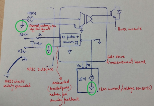
Note:
- It would be good to describe a little better the GND connections you have between the power module and the rest of the system, including the PC you are using. I am assuming those tie together somewhere.
09-23-2014 12:46 PM
BMac,
Sorry about one error in the diagram above. We are not actually grounding the AIX- pin. I will send you an email with the ground connections, block diagram and my preferred time.
