- Document History
- Subscribe to RSS Feed
- Mark as New
- Mark as Read
- Bookmark
- Subscribe
- Printer Friendly Page
- Report to a Moderator
- Subscribe to RSS Feed
- Mark as New
- Mark as Read
- Bookmark
- Subscribe
- Printer Friendly Page
- Report to a Moderator
Course Linkage: Linear Circuit Analysis >> Resistive Circuits >> Voltage Dividers
Measurement Techniques: ELVISmx DMM (voltmeter and ohmmeter)
<hr width="75%">
Introduction
Overview: A voltage divider is any part of a circuit in which a voltage appears across two or more series-connected elements. The voltage "divides" (or distributes) across each element proportionally based on the resistance of the element. Voltage dividers are of fundamental importance as a circuit analysis technique and also find practical application to produce specific voltage levels from a system’s power supply.
Objectives: In this mini-lab you will:
- Measure the voltages of a multi-resistor voltage divider
- Calculate the voltages using the voltage divider equation
- Compare the calculated and measured values
Demonstration: The following video demonstrates the voltage divider concept with incandescent light bulbs and a power supply:
Equipment
- NI myDAQ
- Breadboard
- Alligator clip test leads
- Five resistors, 1/4-W 5% carbon film: 10K, 22K, 33K, 47K, and 100K (see Resistor Color Codes at All About Circuits)
Deliverables
- Submit your work in the form of a homework set problem or lab notebook entry according to the requirements of your instructor.
- Submit your work for each underlined boldface item, and clearly label the item with its section letter and task number.
A. Experience the voltage divider by measurement:
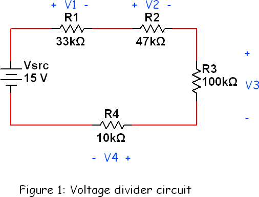
- Draw the circuit of Figure 1.
- Before you construct the circuit, measure and record each resistor value with the ELVISmx DMM ohmmeter. The next video shows the measurement technique and expected typical results:
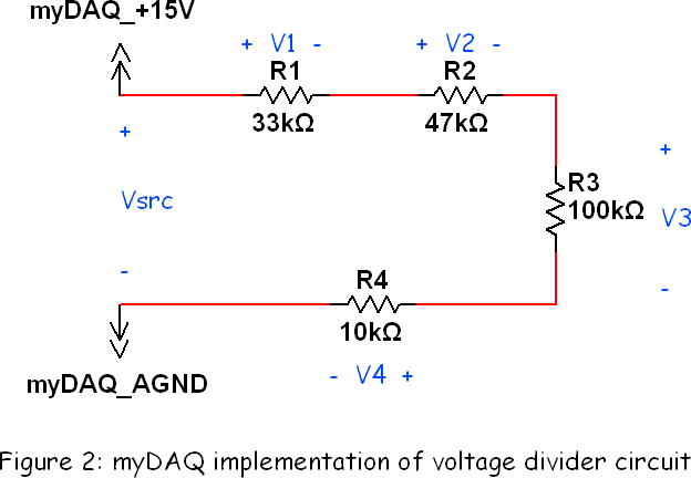
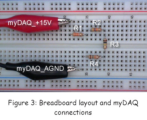
- Construct the circuit of Figure 2 with myDAQ and a breadboard; see Figure 3 for the recommended layout:
- Measure and record each of the five labeled voltages with the ELVISmx DMM voltmeter. The following video shows the measurement technique and expected typical results:
- The "voltage divider" concept suggests that the source voltage Vsrc "divides" (or distributes) across each of the four resistors; each resistor gets its own "piece of the pie," so to speak. Confirm that the "pie pieces" combine back to the whole: add the voltages V1 through V4 and compare this sum to Vsrc.
- Reach a conclusion: What appears to be the relationship between the size of a "pie piece" (resistor voltage) and it associated resistor value?
B. Learn the underlying principles:
The following video tutorial explains the voltage divider principle and derives the equation you can use to calculate the voltage drop across and individual resistor given the source voltage and other resistor values:
C. Connect the principles to your measurements:
- Find a 22K resistor; measure and record its value.
- Replace the resistor R3 with the 10K resistor.
- Measure and record each of the five labeled voltages with the ELVISmx DMM voltmeter.
- Calculate the four voltages V1 through V4 with the voltage divider equation using the measured resistor values and the measured value for Vsrc.
- Calculate the relative difference between the measured voltage and the calculated voltage for each of the four voltages V1 through V4; compute relative difference as "measured value minus calculated value divided by calculated value times 100%."
- Tabulate your results for parts 3, 4, and 5 of this section.
- Evaluate your results: How well does the voltage divider equation predict your measurements?
D. Build your intuition:
Reflect on the following points:
- Choose one answer: A larger resistor value will drop a [ larger | smaller ] portion of the available source voltage.
- Respond: What condition must hold to apply the voltage divider equation?
For more information
