Turn on suggestions
Auto-suggest helps you quickly narrow down your search results by suggesting possible matches as you type.
Showing results for
Document Options
- Document History
- Subscribe to RSS Feed
- Mark as New
- Mark as Read
- Bookmark
- Subscribe
- Printer Friendly Page
- Report to a Moderator
Document options
- Subscribe to RSS Feed
- Mark as New
- Mark as Read
- Bookmark
- Subscribe
- Printer Friendly Page
- Report to a Moderator
Course Linkage: Linear Circuit Analysis >> Resistive Circuits >> Voltage Dividers
Measurement Techniques: ELVISmx DMM (voltmeter and ohmmeter)
<hr width="75%">
Introduction
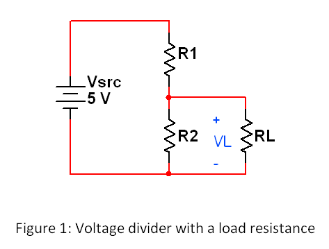
Overview: The voltage divider is commonly used to produce a specific voltage level from the system power supply. For example, a comparator circuit can compare a temperature sensor voltage to a constant threshold voltage established by a voltage divider to indicate a fault condition when the temperature is too high. The voltage divider’s output remains at its desired level only when the connected circuit (called the "load") does not draw significant current.
Objectives: In this mini-lab you will:
- Measure the unloaded and loaded voltages of several voltage dividers
- Evaluate the performance of the voltage dividers due to loading
- Predict the minimum load resistance that will maintain a voltage divider’s output within a specified range
Demonstration: The following video demonstrates four voltage dividers, each designed to produce the same voltage level. An LED (light-emitting diode) serves as the load to indicate the degree to which each voltage divider can maintain its intended voltage. The ability to maintain a given voltage level comes at a cost, though; watch the video and find out why:
Equipment
- NI myDAQ
- Breadboard
- Connecting wire
- Alligator clip test leads
- Resistors, ¼-W 5% carbon film:
- 100 ohm (two)
- 1.0 Kohm (two)
- 10 Kohm (two)
- 10K potentiometer
- Switches (three)
Deliverables
- Submit your work in the form of a homework set problem or lab notebook entry according to the requirements of your instructor
- Submit your work for each underlined boldface item, and clearly label the item with its section letter and task number
A. Experience voltage divider loading by measurement:
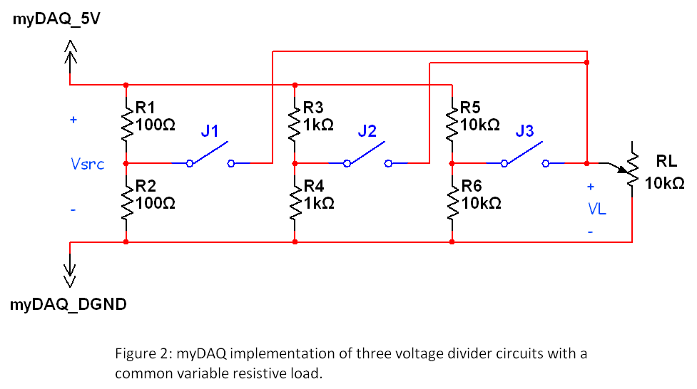
- Figure 1 shows a two-resistor voltage divider with a resistive load. Figure 2 shows three voltage dividers that can be individually connected to a single variable load via switches. Draw Figure 2.
- Measure and record each of the six resistors listed in the "Equipment" section.
- Measure and record the resistance of your 10K potentiometer; make the measurement between the outer two terminals, often numbered "1" and "3".
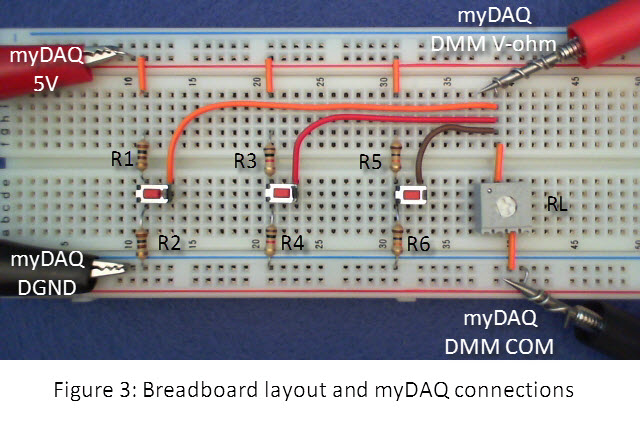
TIP: This resistance does not change as you turn the potentiometer dial. - Construct the circuit of Figure 2 with myDAQ and a breadboard; see Figure 3 for the recommended layout. This circuit makes it easy to connect a single load to any one of three available voltage dividers. You may use a short jumper wire if you do not have three switches handy, although take care to only connect one voltage divider at a time.
- Connect the DMM probes permanently to the potentiometer to save effort. Use probe clips if you them available, or coil a wire around the probe tip with one end of the wire long enough to connect into the breadboard.
TIP: Wrap the wire around the probe tip to form a coil, remove the coil and bend it slightly, and place it back on the coil (bending the coil ensures a snug fit):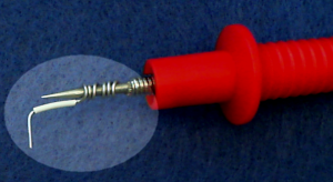
- Measure and record the myDAQ 5V supply voltage; this is labeled as Vsrc on the circuits of Figures 1 and 2.
- Remove the potentiometer. Set the DMM to voltmeter mode, DC, and autoranging mode. Close the switch for the 100-ohm resistor voltage divider; measure and record the unloaded voltage. Repeat for the other two voltage dividers. Expect to see each voltage very close to half the value that you measured in the previous step.
- Replace the potentiometer. With all three switches open, change the DMM to ohmmeter mode.
IMPORTANT: Make sure that all switches are OPEN when you use the DMM as an ohmmeter. The ohmmeter applies its own current to the resistor and measures the resulting voltage to calculate resistance, consequently the resistor MUST be disconnected from the rest of the circuit during this measurement. You can damage the ohmmeter by connecting it into a live circuit! - Adjust the potentiometer dial with a screwdriver until the measured value reads 10K; you may find that the maximum value is slightly less than this nominal value. Record the measured value at this dial setting as the current load resistance RL.
- Change the DMM back to voltmeter mode.
- Close the switch for the 100-ohm voltage divider, record the measured voltage VL, and then open the switch again.
- Close the switch for the 1-Kohm voltage divider, record the measured voltage VL, and then open the switch again. Repeat for the 10-Kohm voltage divider.
- Change the DMM back to ohmmeter mode, and adjust the potentiometer dial until the measured load resistance is 8K; record your actual value.
- Change the DMM back to voltmeter mode, and measure and record the load voltages for each of the three voltage dividers; remember to only close one switch at a time.
- Repeat Steps 13 and 14 to create a data table of measured load resistance (RL) and load voltages (VL) for RL changing 2-Kohm steps; if you have time, you may wish to create a more detailed table by changing RL in 1-Kohm steps.
- Visualize your data table as a graph; plot the measured load voltages VL as a function of load resistance RL. Plot your data curves for each of the three voltage dividers on the same graph.
- Discuss your results: Describe the ability of each voltage divider to maintain a constant voltage output across the full range of load resistances between 2 Kohm and 10 Kohm.
See the following video clip for the measurement technique and expected results:
B. Learn the underlying principles:
The following video tutorial explains how the loading effect changes the desired output of a voltage divider and derives an equation you can use to predict the effect of loading. The video tutorial also discusses the relative advantages and disadvantages of the choice of voltage divider resistors.
C. Connect the principles to your measurements:
- Calculate the expected voltage divider value VL for each of the three voltage dividers for a load resistance of 3.50 Kohm. Use your measured values for R1 and R2 in this calculation.
- Set the potentiometer to 3.50 Kohm and then measure and record the load voltage for each of the three voltage dividers.
- Evaluate your results: Compare your expected values of VL to your measured values.
D. Build your intuition:
Reflect on the following points:
- Choose one answer: A voltage divider constructed with low-valued resistors will produce a [ less stable | more stable ] voltage for a range of load resistance.
- Choose one answer: A voltage divider constructed with low-valued resistors will require [ less current | more current ] from the power supply.
- Study the plots you created in Section A and create a rule-of-thumb that you can use in other projects by completing this sentence: "The minimum load resistance should be a factor of ___ times the voltage divider resistor size to ensure a stable voltage."
For more information
