- Document History
- Subscribe to RSS Feed
- Mark as New
- Mark as Read
- Bookmark
- Subscribe
- Printer Friendly Page
- Report to a Moderator
- Subscribe to RSS Feed
- Mark as New
- Mark as Read
- Bookmark
- Subscribe
- Printer Friendly Page
- Report to a Moderator
Overview:
This document describes how to set up an automatic modulation classification (AMC) system through cyclostationary feature detection (CSD) using NI LabVIEW software and NI USRP™ (Universal Software Radio Peripheral) hardware. After a brief discussion of AMC and CSD, the paper examines the hardware and software based on LabVIEW for an automatic modulation classifier that is capable of classifying among four modulation schemes: BPSK, QPSK, FSK, and MSK.
Table of Contents
1. What Is AMC?
2. AMC using CSD
3. Implementing an AMC system using CSD
4. AMC-CSD: Hardware Configuration
5. AMC-CSD: Software Configuration
6. Working With the Example
7. Building an AMC-CSD System in LabVIEW
i. Different Modulation Schemes for Transmission
ii. Designing the Cyclic Feature Detector
8. Results
9. Additional Resources
What is AMC
AMC is the automatic recognition of the modulation format of a sensed signal. For an intelligent receiver, AMC is the intermediate step between signal detection and demodulation. The purpose of AMC algorithms in a radio receiver is to identify the existence of a signal in a particular frequency band at a given location, and then determine the modulation type being employed in the spectrum. A large number of modulation classification methods have been developed and they have been traditionally grouped into two broad categories, likelihood-based and feature-based methods. This paper focuses on one of the feature based methods: AMC algorithms using cyclostationary features.
AMC using CSD
Some modulation classification algorithms are based on the use of signal cyclostationarity. This technique also falls under the category of feature based methods. This type of algorithm can be applied to linear modulation classification and to low SNR signals. Many signals can be modeled as cyclostationary rather than wide-sense stationary, due to their underlying periodicities. For such processes, both their mean and autocorrelation are periodic. A spectral correlation function (SCF) can be obtained from the Fourier transform of the cyclic autocorrelation. A maximum value of normalized SCF over all cycle frequencies gives the cycle frequency domain profile (CDP). Several modulation schemes have unique CDP patterns, which can be used as a discriminator in the classification process.
Many signals encountered in practice have parameters that vary periodically with time. Examples include radar signals and periodic keying of amplitude, phase, or frequency in digital communication systems. In conventional receivers, these periodicities are usually not explored for extracting information or parameters. The performance of signal processing can be improved in many cases by considering these hidden periodicities.
Implementing an AMC system using CSD
The AMC system described here uses cyclic feature detection on the receiver side to classify among BPSK, QPSK, FSK, and MSK modulation schemes. The transmitter selects one of these four modulation schemes to transmit a randomly generated stream of bits. The receiver, upon receiving the signal, extracts its cyclostationary features (spectral coherence function and cyclic domain profile) and uses a trained neural network to classify the modulation scheme.
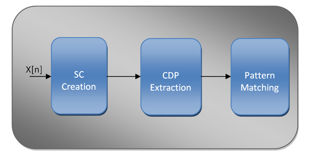
Figure 1: Block Diagram of AMC using CSD
AMC-CSD: Hardware Configuration
You need two NI USRP transceivers because individual transceivers are not capable of two simultaneous transmit or receive. The following configuration is recommended:
· One PC with a free Gigabit Ethernet port.
· One Gigabit Ethernet switch connected to the PC.
· The first transceiver connected directly to the switch via Ethernet. This is your transmitter.
· The second transceiver connected to the first one via MIMO cable to ensure the synchronization between the transmitter and the receiver. This is your receiver.
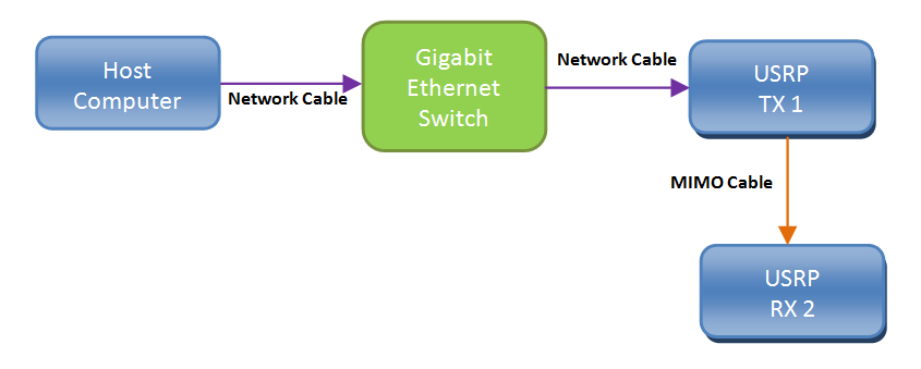
Figure 2: The AMC-CSD Hardware Setup Diagram
Figure 2 shows the configuration of the AMC-CSD system that facilitates the synchronization between the reference clock sources of the transmitter and the receiver. Each transceiver has one antenna connected to either port (NI recommends RX1/TX1 for simplicity). For desired operation, the transmitter should be at least half a wavelength of the carrier frequency used apart (the same is true for the receiver).
AMC-CSD: Software Configuration
This AMC-CSD example is a LabVIEW application that requires the following software components:
· NI LabVIEW Version 2011 (or later) system design software—Full, Professional, or Student Edition
· NI-USRP Version 1.1
· NI LabVIEW Modulation Toolkit Version 4.3.1
· AMC-CSD Example VIs
Working with the Example
Unzip the associated zip file to a new folder and open the file entitled mod_classifier_TX.vi and mod_classifier_RX.vi in LabVIEW.
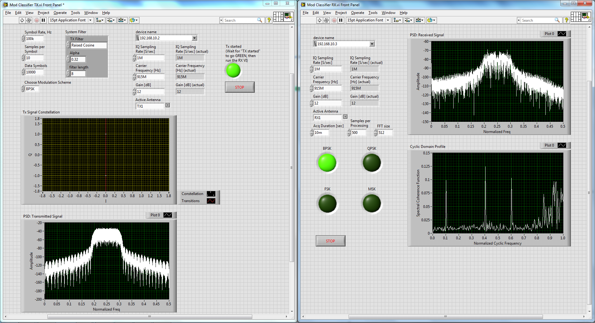
Figure 3: Front panel of the mod_classifier_TX.vi and mod_classifier_RX.vi
The front panels of the example VIs contain the parameters for the TX and RX of NI USRP transceivers, respectively. Set the controls of these parameters with the following guidelines in mind:
USRP IP Address: Enter the two IP addresses associated with the NI USRP transceivers in each of the TX and RX VIs.
I/Q Sampling Rate [S/sec], Symbol Rate, Samples per Symbol: For the I/Q Sampling Rate, enter the sample rate, in units of samples per second, for the baseband I/Q signal samples for both the TX and RX. Enter values for the Symbol Rate, and Samples per Symbol so that the I/Q Sampling Rate is an even multiple of the desired Symbol Rate. Enter an even-valued Samples per Symbol that corresponds to the multiple. In other words, the relationship between the I/Q Sampling Rate, Symbol Rate, and Samples per Symbol parameters needs to be as follows:
I/Q Sampling Rate = Symbol Rate * Samples per Symbol
Modulation Scheme: Choose the desired modulation scheme to be classified from a pool of four modulation schemes: BPSK, QPSK, BFSK, and MSK.
Data Symbols: In this case data equivalent to 10 ms duration is considered. This can be adjusted accordingly.
System Filter: System Filter cluster provides the pulse shaping filter parameters. For this example a Raised Cosine filter of length 8 is used.
With the parameters set appropriately, you can run the VIs. Doing so; the TX starts to continuously transmit modulated signal. The RX upon receiving the modulated signal performs classification and the classification results are displayed in the RX VI.
Building an AMC-CSD System in LabVIEW
This section describes the key components of the AMC-CSD system:
i. Different Modulation Schemes for Transmission:
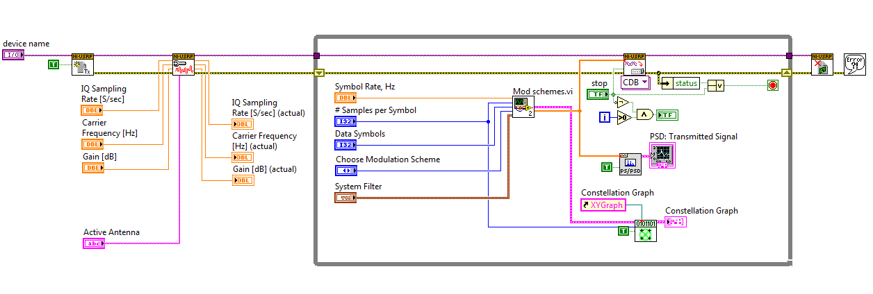
Figure 4: Block diagram of the mod_classifier_TX.vi
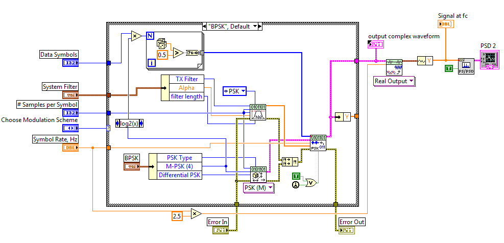
Figure 5: Block diagram of the Mod schemes.vi
Figure 4 presents the block diagram of the mod_classifier_TX.vi. As can be seen from the block diagram, the mod-classifier_TX.vi calls the subVI Mod schemes.vi to provide the desired modulated signal. The block diagram of the Mod shemes.vi is given in Figure 5.
ii. Cyclic Feature Detector and Modulation Classification
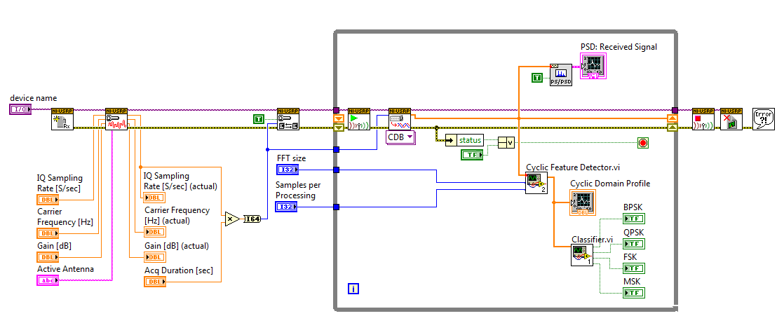
Figure 6: Block diagram of the mod_classifier_RX.vi
As can be seen from the block diagram of mod_classifier_RX.vi (Figure 6), the RX VI captures the transmitted signal and provides the received signal along with other required parameter values to the Cyclic Feature Detector.vi subVI. This subVI returns back the cyclic domain profile (CDP) of the received signal. The block diagram of the Cyclic Feature Detector.vi subVI is presented in Figure 7:
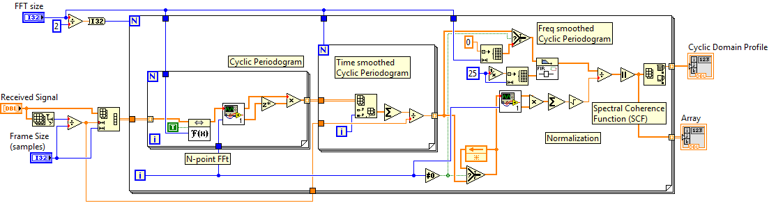
Figure 7: Block diagram of the Cyclic Feature Detector.vi
Figure 7 explains the steps included in calculating the cyclic domain profile of the received signal. First the cyclic periodogram of the received signal is calculated using N-point FFT. These FFT values are then smoothed both in time and frequency domain and normalized to generate the spectral coherence function (SCF) of the received signal. Then the cyclic domain profile is calculated for each cycle frequency from the spectral coherence function.
The 2nd subVI that the mod_classifier_RX.vi calls, as can be seen in Figure 6, is the classifier.vi. The RX VI inputs the cyclic domain profile to the classifier.vi and it returns back the classification results. Usually For pattern matching, neural networks or the hidden Markov model are employed. While using neural networks, training sequences are used initially to get the networks familiarized with the patterns associated with different modulation schemes. Then this trained network is used to classify the received signal.
Results
Figure 3 shows the results from a test run of the AMC-CSD system running on two NI USRP transceivers. The front panel of the mod_classifier_TX.vi presents the PSD and signal constellation of the transmitted signal. The front panel of the mod_classifier_RX.vi presents the PSD of the received signal. The PSDs of the transmitted and received signals confirm that we are dealing with the same signals. The RX VI front panel also provides the cyclic domain profile (CDP) and the detected modulation scheme. This image shows that the AMC-CSD system works properly. The Cyclic Domain profile and the Spectral Coherence Function of BPSK, QPSK, BFSK, and MSK are given bellow:
i. BPSK:
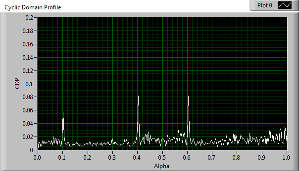
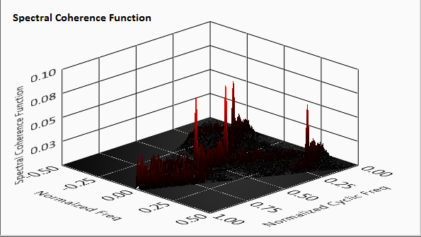
Figure 8: CDP and Spectral Coherence Function for BPSK
ii. QPSK:
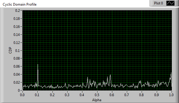
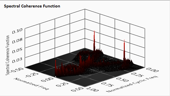
Figure 9: CDP and Spectral Coherence Function for QPSK
iii. BFSK:
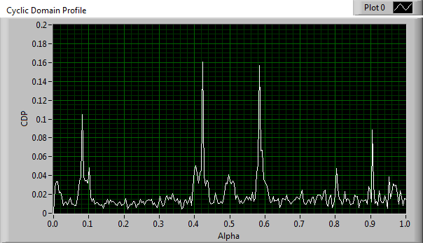
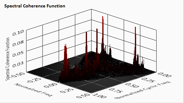
Figure 10: CDP and Spectral Coherence Function for BFSK
iv. MSK:
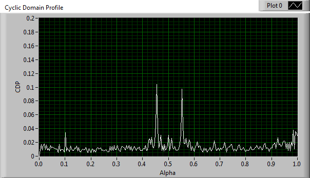
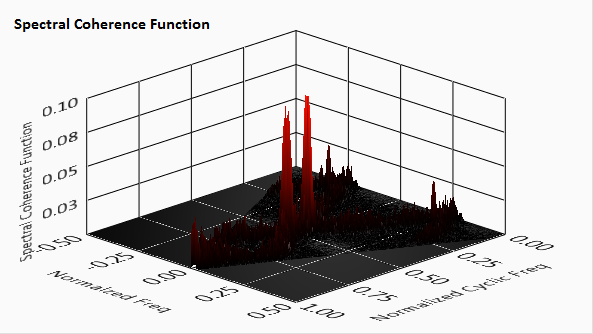
Figure 11: CDP and Spectral Coherence Function for MSK
Additional Resources
B. Ramkumar, “Automatic Modulation Classification for Cognitive Radios using Cyclic Feature Detection.” IEEE Circuits and Systems Magazine, Volume: 9, Issue: 2, Pages: 27-45, 2009.
- Mark as Read
- Mark as New
- Bookmark
- Permalink
- Report to a Moderator
Thanks msohul
i tried your program its working on usrp
now if i want to try it with another code
can you give me hint about cyclic domain profile how i can apply it to any system for classify incoming signal
or at least guide how to understand principle of work and if there are another algorithms do same function ..
Thanks
- Mark as Read
- Mark as New
- Bookmark
- Permalink
- Report to a Moderator
Hello sir,
I am M.E student , I am facing lots of problem in my project can you please guide,using USRP 2920 can we sense TV band using the above cyclic feature detector code.
