- Document History
- Subscribe to RSS Feed
- Mark as New
- Mark as Read
- Bookmark
- Subscribe
- Printer Friendly Page
- Report to a Moderator
- Subscribe to RSS Feed
- Mark as New
- Mark as Read
- Bookmark
- Subscribe
- Printer Friendly Page
- Report to a Moderator
digsys-03: Implementation Styles for Combinational Circuits
Introduction
LabVIEW FPGA offers a wide range of styles to express a combinational circuit. This tutorial presents seven ways to implement a given circuit, including familiar traditional techniques found in digital logic textbooks as well as techniques likely to occur to experienced LabVIEW programmers.
This tutorial also presents a complete audio meter application in which a host VI plays a .wav audio file on the sound card while simultaneously transferring real-time audio level values to the FPGA development board that are decoded by the FPGA to drive a linear LED array as a bar graph style audio meter.
Audio Meter Application Example
The audio meter demonstrated below is the subject of this tutorial:
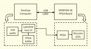
Introductory digital courses open with combinational logic circuits, also known as combinatorial circuits. A “bar graph decoder” circuit that translates measured audio level into an LED pattern provides a motivating example for students. The bar graph decoder circuit resides on the FPGA target, and slide switches provide inputs for initial testing and debugging. Because LabVIEW FPGA provides ongoing communication via USB cable between the desktop and the FPGA development board after FPGA configuration, it is a relatively simple matter for a desktop VI (or host VI) to read and process an audio file and send values directly to the bar graph decoder input every 100ms. The complete system looks like this:
General Considerations for LabVIEW FPGA VIs
LabVIEW VIs intended for the FPGA target require special consideration. The scope of available subVI palettes is dramatically reduced compare to those available for a desktop application VI, floating point data type is not supported, and variable-size and multidimensional arrays are not supported, among other restrictions (see the LabVIEW help page on "Unsupported LabVIEW Features -- FPGA Module"). For basic digital circuits, the desired functionality must be enclosed in a while-loop structure, otherwise the circuit will appear to "run" one time and then quit. The following video continues the discussion of the while-loop structure, and also shows how to connect the circuit to the FPGA I/O pins:
Bar Graph Decoder Circuit
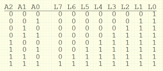
The bar graph decoder combinational circuit translates a 3-bit unsigned integer into eight signals to drive a linear array of LEDs on the FPGA development board. An input value of 0 activates one LED, a value of 1 activates two LEDs, and so on. The following truth table specifies the complete input/output behavior of the combinational circuit where “A” signifies the audio input and “L” denotes the LED:
The bar graph decoder functionality can be expressed in a variety of ways, all leading to identical circuit behavior. The next two sections detail traditional methods such as logic gate schematics and VHDL descriptions as well as methods likely to occur to programmers with LabVIEW “G” coding experience.
Traditional Implementation Styles
The following videos detail four traditional implementation styles for the bar graph decoder combinational circuit: logic gate schematic, 3-to-8 decoder plus glue logic, ROM lookup table, and VHDL description. Each video explains the implementation style, and also illustrates block diagram construction techniques relevant to the particular coding style.
All of the files discussed in this tutorial are available in the LabVIEW project “audio_meter.zip” linked at the bottom of this document. Always open the VIs from within the project window, otherwise the FPGA-targeted VIs will open incorrectly. The original VHDL file shown in the video is also linked at the end of this document.
G-Code Implementation Styles
These videos discuss three implementation styles that would likely occur to a LabVIEW programmer seeking to satisfy the functional requirements of the circuit with no knowledge of the techniques described in digital circuits textbooks. These styles include: array of comparators, case structure, and mathematical equation.
Host VI Control of FPGA Target
Controlling the bar graph decoder from the desktop computer via the USB cable is a pleasantly straightforward task in LabVIEW FPGA. This video describes a basic communication scheme between a host-based VI and an FPGA-targeted VI:
The following video describes the audio meter host VI that first configures the FPGA target with a specific bitstream file (the logic gates version of the bar graph decoder) and then subsequently sends audio frames to the soundcard and measured audio levels to the FPGA; note that the FPGA circuit has been modified to use standard front panel controls rather than slide switches:
Conclusion
The LabVIEW FPGA programming environment provides many ways to express a combinational logic circuit. Support for traditional methods such as logic gates, VHDL descriptions and ROMs -- as well as a full range of sequential logic styles -- positions LabVIEW FPGA as a viable development platform for digital circuits and systems course laboratories.
Moreover, the desktop-to-FPGA communications offered by LabVIEW FPGA open new ways for student-designed FPGA systems to interact with external surroundings. The audio meter presented in this tutorial represents only a simple example of what can be accomplished, yet points to a multitude of projects that can leverage the strengths of the desktop computer – graphical user interface, advanced numerical analysis, file and network access, to name a few – as a new and exciting “peripheral device” for the FPGA system.
- Mark as Read
- Mark as New
- Bookmark
- Permalink
- Report to a Moderator
No sound in "VHDL Implementation" video?
- Mark as Read
- Mark as New
- Bookmark
- Permalink
- Report to a Moderator
Thanks for the tip, I have repaired this video.
