- Subscribe to RSS Feed
- Mark Topic as New
- Mark Topic as Read
- Float this Topic for Current User
- Bookmark
- Subscribe
- Mute
- Printer Friendly Page
how to create Hardware abstraction layer
04-01-2014 12:26 PM
- Mark as New
- Bookmark
- Subscribe
- Mute
- Subscribe to RSS Feed
- Permalink
- Report to a Moderator
This is where you started, isn't it? Sensor controller and Cylinder within one class!? You can definetly do it this way, but as you already relaized you would end up with alternate classes, where you have to copy and paste code to for example read sensors or write valves.
When you seperate classes for sensor and cylinder, you can reuse their code. They don't need to be actors. You could also include them in the private data of your Control Actor. Here is a good application, where hardware is implemented as object within an actor:
https://decibel.ni.com/content/docs/DOC-21441
Attached find an example how you could create a solution with three actors for your application. I hope it helps 
Edit: Think about a Launch Structure like that...
You're free to make your code as it suites you. But for the sake of reusibility I would recommend to make it in three components: Sensor, Controller, Cylinder
...in the real world (hardware) you would also hook up cylinder and sensors to a control unit. Why not do this in the virtual world (software)?
Of course in the real world you could also have a complete cylinder unit with sensor, controller and cylinder. But this mostly doesn't give you the flexibilty to easily remove, replace or upgrade parts! In the software world it is the same.
04-02-2014 03:44 AM
- Mark as New
- Bookmark
- Subscribe
- Mute
- Subscribe to RSS Feed
- Permalink
- Report to a Moderator
Yes this is way on started. Now it is little better :). I separated hardware in order to I could use more types Hardware (Simulated, DAQmx HW mono cylinder with 2 sensors and bistable cylinder with 1 sensor).
Logic for cylinder is same for all cylinders. Cylinder must read status from sensor than do something and write to output correct state. Only layers hardware is changed because i have more types cylinders ( monostable with 0Sensor ... nSensors and bistable with 0Sensor...nSensor) monostable has one valve, bistable has two valves.
Therefore, it is not clear to me why you want create sensor actor which has the task: read status of sensors?
04-02-2014 10:11 AM
- Mark as New
- Bookmark
- Subscribe
- Mute
- Subscribe to RSS Feed
- Permalink
- Report to a Moderator
Logic for cylinder is same for all cylinders.
To me it can't be the same logic... you have three input variants (0-2 sensors) and two output variants (mono-/bistable). To me this must create six different logics.
Therefore, it is not clear to me why you want create sensor actor which has the task: read status of sensors?
I didn't exactly said that... I don't necessarly want to create an actor but an object. This way you can use the same "read sensor" code for both cylinder variants. The more variants you use the important this gets. Just look at your example with and without sim. Without sim you have 2(cylinders) x 3(sensors) = 6(objects). When you add sim to your code you get 2(sim/hw) x [2(cylinders) x 3(sensors)] = 12(objects). If you want to simulate sensor OR cylinder independently you will get [2(sim/hw) x 2(cylinders)] x [2(sim/hw) x 3(sensors)] = 24(objects).
The way I'd do it is create 6(logics) + 2(sim/hw) x 2(cylinders) + 2(sim/hw) x 2(sensors) = 14(objects) (0 sensor logics don't need a sensor object). So you'd need 10 less objects to create the flexibility to simulate sensor OR cylinder. Plus it's much easier to replace, add or maintain code...
Let's say you want to test another data acquisition system. You would end up with maybe 3(sim/hw1/hw2) x 2(cylinder) x 3(sensors) = 18 objects if you replace input AND output. If you want to replace input OR output it would be [3(sim/hw1/hw2) x 2(cylinders)] x [3(sim/hw1/hw2) x 3(sensors)] = 54(objects).
Now with three hierachies you would need 6(logics) + 3(sim/hw1/hw2) x 2(cylinders) + 3(sim/hw1/hw2) x 2(sensors) = 18(objects) to create the same flexibility as you get with 54(objects) in one hierachy.
If you go further and your systems actually allows you to read and write one sensor and valve at the time, the logic objects could decide how many sensors and valves they need. Your structure would go down to 6(logics) + 3(sim/hw1/hw2) x 1(valve) + 3(sim/hw1/hw2) x 1(sensor) = 12(objects)
I hope that clarifies, why I would use reusable code
04-03-2014 12:57 AM
- Mark as New
- Bookmark
- Subscribe
- Mute
- Subscribe to RSS Feed
- Permalink
- Report to a Moderator
To me it can't be the same logic... you have three input variants (0-2 sensors) and two output variants (mono-/bistable). To me this must create six different logics.
Yes, you have true I have more input variants and two output variants but i don't create six different logic. Because standard cylinder has one valve and two Sensors.
And I want create abstract class CYLINDER. This class has dynamic dispatch methods Configure, Close, Read, Write and Static method Logic. For simulated and real HW owerride this methods for every child class special behavior but Output it has same like abstract class.
For example:
For cylinder logic I need two Sensor to know correct position and output False is idle position True is busy position. If I have Monostable cylinder with one sensor in dynamic dispatch method Read i will simulate second sensor this output is negative to real sensor.
And also it will be with output for bistable cylinder.False is idle position True is busy position change is in dynamic dispatch for this cylinder when are two valves (Idle position: V1->on & V2->off , Busy position V1->off & V2->on) input is same like abstract class "Direction" (False or True). Therefore I think that cylinder has same logic. I create only specific dynamic dispath for read status from sensor and write output to valve.
04-03-2014 08:36 AM
- Mark as New
- Bookmark
- Subscribe
- Mute
- Subscribe to RSS Feed
- Permalink
- Report to a Moderator
Ok... I see... Well if you only consider to create two variants it's much of a deal. You don't need much flexibility for that. But the two hierarchy graphs you posted here were showing a different approach, where you would consider to create all kind of combinations. I just wanted to give you an idea how you could create those combinations with minimized effort.
04-03-2014 09:05 AM
- Mark as New
- Bookmark
- Subscribe
- Mute
- Subscribe to RSS Feed
- Permalink
- Report to a Moderator
For this application I need only two variants (monostable with 2 sensors & bistable with 2 sensors) but to future I will need more variants 😉
I know what you mean but this time I am little confused from it. Because I am looking on sample example Evaporative cooler and I want create something like this.
My problem now is how to create manipulator actor throught composition cylinder actors. Manipulator actor is caller and 4 cylinders are nested actors. Manipulator is state machine. He do something if previous command finished OK but if previous command finished wrong send message to his caller.
Manipulator have UI for servis mode.
Edit: on picture is sketch cylinder object which i want do.
04-04-2014 01:47 PM
- Mark as New
- Bookmark
- Subscribe
- Mute
- Subscribe to RSS Feed
- Permalink
- Report to a Moderator
Take a look at the example and check out how the "Evaporative Cooler.lvclass" controls the fan. The evaporative cooler only has temperature as input, so it's combined with the controller. Since you want to have different input for multiple controllers it's better to seperate.
Maybe check out the example I attached for you in my previous post. It's just missing the trigger... but other than that it should be what you want! You just need to...
- create two childs from "Controller.lvclass" for "Bistable with 2 Sensors" and "Monostable with 1 Sensor"
- define logic by overwriting "Set Feedback.vi"
- create the trigger
- create a child from "Sensor.lvclass" for "2 Sensor"
- define HW read by overwriting "Acquire Data Core.vi"
- create a child from "Cylidner.lvclass" for "Bistable"
- define HW writes by overwriting "Set Valves.vi"
I added the messages to the Launch Structure I posted before. Maybe that helps with the confusion 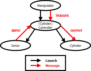
04-05-2014 10:50 AM
- Mark as New
- Bookmark
- Subscribe
- Mute
- Subscribe to RSS Feed
- Permalink
- Report to a Moderator
My previous picture represent object Cylinder with inpout and output. Input is Direction (True or False) and Output is Busy (True or False).
For example:
Manipulator send trigger & Direction to Lift and then wait or check Busy state. Inside in Cylinder is sequence (idle ->position? –> move -> position? -> idle) and next I am added behavior time? and retry.
Cylinder sends message to manipulator about this whether is cylinder busy or ready.
Edit:
Cylinder object waiting on trigger & Direction from manipulator and than start sequence: position? -> move -> position? -> Idle (send to manipulator Ready and wait on next trigger & Direction)
04-08-2014 05:29 AM
- Mark as New
- Bookmark
- Subscribe
- Mute
- Subscribe to RSS Feed
- Permalink
- Report to a Moderator
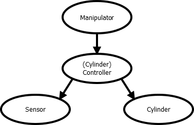
Yours picture represents :
Driver of cylinder manage physical units (sensors & valves). Cylinder controller manage driver and communication with Caller.
Driver has tasks: check time, check position and set valve state. Cylinder controller Run and Reset driver and announces to caller state of the cylinder ( Busy or Error) Error status will be when elapsed time on execution task. Cylinder controller must ensure to driver not be receive message as far as driver is performed.
04-09-2014 08:37 AM
- Mark as New
- Bookmark
- Subscribe
- Mute
- Subscribe to RSS Feed
- Permalink
- Report to a Moderator
That's almost my idea of it... but "Cylinder Controller" would be the "driver" for the whole function, while "Sensor" and "Cylinder" are drivers for I/O either hardware and simulation.
But other than that you're right:
"Cylinder Controller" could have commads like: set direction, trigger, check busy state
"Cylinder Controller" could have tasks like: check time, check position and set valve
"Cylinder Controller" descendants would be "Bistable - 1 Sensor" and "Monostable - 2 Sensor". They would include appropiate I/O driver and overwrite "check position" and "set valves".
The example I uploaded for you is similar... The difference is that "Cylinder Controller" is not polling the sensor state, but "Sensor" is triggering "check position" by sending its state.
Anyway... as Nike says: "Just do it." Any solution that works is a good solution
