- Document History
- Subscribe to RSS Feed
- Mark as New
- Mark as Read
- Bookmark
- Subscribe
- Printer Friendly Page
- Report to a Moderator
- Subscribe to RSS Feed
- Mark as New
- Mark as Read
- Bookmark
- Subscribe
- Printer Friendly Page
- Report to a Moderator
1000 Products, One Single Board RIO (all is needed a little bit ...file!)
NI sbRIO-96XX Series DIO/MIO Breakout and Development System
Overview
The flexibility and ease of use of the NI single-board RIOs has helped us to develop numerous and diverse products in a relatively short time. We have assembled a general purpose and very cost effective embedded control and acquisition system that can be programmatically change from one product to another. See the Slide show demonstrating the sbRIO's Development system.
The development system consist of a specially designed breakout and a daughter board (Personality Module) combined with power supply and a temperature controlled fan that are housed inside an attractive wall mounted case (URL) with easy access to all inputs and outputs via terminal blocks. The development system also includes, NI sbRIO-9626 embedded control and acquisition device with NI 9636 2-slot C series RMC module that can be populated with any compatible C series modules. Figure 1 shows the block diagram for the development system. Figure 2 shows the assembled sbRIO Development system.
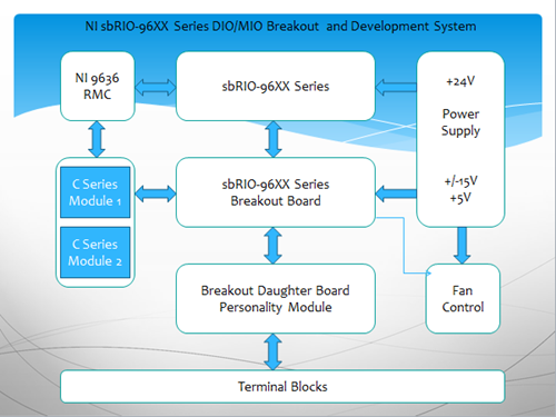
Figure 1: sbRIO Development System Block Diagram
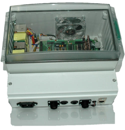
Figure 2: sbRIO Development System
The Breakout Board
The breakout board is a direct-mate to DIO/MIO connectors or can be connected via 50-pin ribbon cable with IDC header. It allows for quick prototyping and assembling of electronic circuits. For example, Figure 3 shows a sample project of an ECG monitoring system with highly isolated DC-DC power supply and ECG output signals. It also provides 4 channels of isolated digital I/O with voltage-level translated from 3.3V FPGA to 5V TTL logic. Most parts on this design are off-the-shelf components and breakout boards such as “Opto-isolator breakout board and Single Lead Heart Rate Monitor from sparkfun.
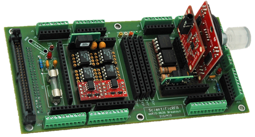 Figure 3: Sample Project of ECG Monitoring System
The Daughter Board (Personality Module)
The daughter board is designed to be mated with the “Breakout Board” with direct access to all input/output signals and power busses from the breakout board and sbRIO system. It can be customized and used for circuits that require large real state on the board such as signal conditioning, power handling devices, power transistors, relays etc. Figure 4 shows four channels of high speed power switching system that we are using to develop few diverse products just by programming the FPGA portion of the system. Figure 5 shows the breakout board combined with the personality module board sandwiched together.
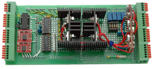
Figure 4: Personality Module (4 Ch High Speed Switching System)
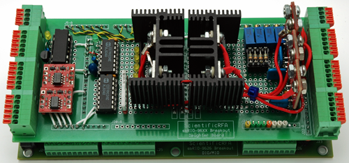
Figure 5: Combined Breakout Board with 4 Ch High Speed Switching Systems
Applications:
We are in process of developing FPGA codes using the above sbRIO development system for the following areas of technology and will publish articles for some of these product as time permits.
Industrial
- Precision Programmable Power Source
- Lead Acid / Li-Ion Battery Charging and Testing System
- DC to AC power inverter (modified sine wave)
- DC to AC power inverter (Pure sine wave)
- Three phase AC power system
- Thermoelectric Heating/Cooling system
- UPS, Emergency power system
Medical
- Radio Frequency Ablation system (RFA)
- Continues Cardiac Output Measuring System (CCO)
- ECG monitoring system
Consumer Electronics
- LED light Dimmer (from 1-99%)
- General purpose light dimmer
- Home heating and cooling system
Research and Development (R&D)
- Programmable Triple Output Power Supply
- Magnetic Design, Core testing, e.g. BH Loop
- Virtual Lab
Comming up Next : LabVIEW FPGA Project Setup and Code Development
