Aircraft Simulator
- Subscribe to RSS Feed
- Mark as New
- Mark as Read
- Bookmark
- Subscribe
- Printer Friendly Page
- Report to a Moderator
Code and Documents
Attachment
Overview
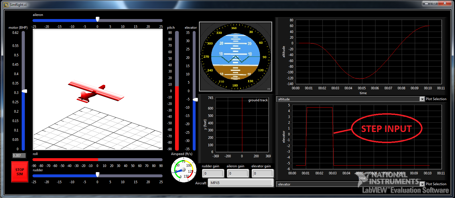
A real-time controllable simulator was created for the purpose of test-flying the aircraft and for testing various feedback control inputs. The following figure illustrates the graphical user interface (GUI) for the simulator.
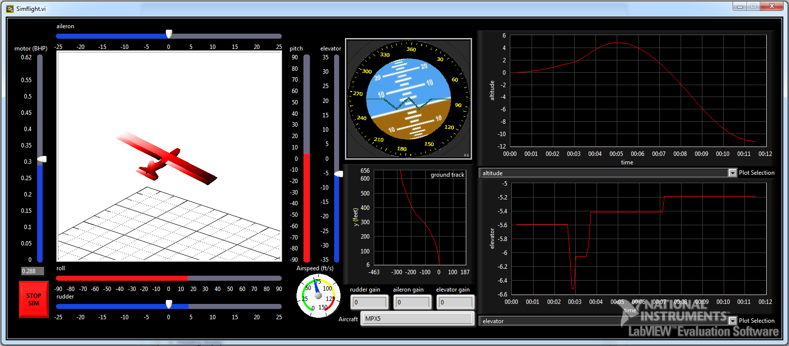
Figure 1: graphical user interface for simulator
GUI display features
- 3-D render of aircraft
- Attitude gimbal display
- Ground track display
- Airspeed indicator
- Control surface input display
- Time plots of any state space variables or outputs
Control inputs
- Elevator
- Aileron
- Rudder
- Throttle
Control input options
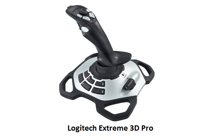
- Joystick (Logitech Extreme 3D Pro)
- user-specified step function (no joystick needed)
- user-specified doublet function (no joystick needed)
- user-specified ramp function (no joystick needed)
Simulator configuration parameters
- Specify aircraft
- Specify aileron proportional feedback gain
- Specify elevator proportional feedback gain
- Specify rudder proportional feedback gain
Joystick Control
The simulation can be controlled in real-time through the use of a joystick. While it's possible that any generic joystick might work with this code, I am only able to guarantee compatibility with the Logitech Extreme 3D Pro joystick. The following figure illustrates the mapping of joystick axes to aircraft control surface input.
|
|
Where: Y = elevator control X = aileron control RZ = rudder control Throttle = motor power |
Figure 2: Joystick configuration for simulator control
Theory of Operation
The following is a summary of the process for simulating the aircraft response in real-time:
- FlatEarth v9.53 generates linearized state space for aircraft dynamics
- MATLAB script exports state space to text config files
- Labview 2015 reads config files on startup
- Labview 2015 Control Design and Simulation Module utilized for performing state space calculations
- Timing logic used to enforce real-time operation
The state space obtained from FlatEarth is illustrated in Figure 3:
Figure 3: FlatEarth state space output to Labview
The state space variables, inputs, and outputs are defined in Table 4.
Figure 4: State Space Variable Definitions
State Space Feedback Control
It is desirable to be able to apply proportional feedback control gains to the aileron, rudder, and elevator for aircraft testing. The figure below illustrates how the open-loop state space is wrapped by a proportional controller.
Figure 5: proportional feedback controller applied to state space [10]
With the addition of the proportional controller, the state space equation can then be written as: [10]
User-Guide
Installation
You will need to install the following elements before being able to run this code:
- LabVIEW 2015 Development system
- LabVIEW Control Design and Simulation Module
- Simflight.zip (at bottom of this page)
Please note that LabVIEW 2015 and the Control Design and Simulation Module can be downloaded/installed for free for a 7-day trial. You can extend this to a 45 day trial by creating a free National Instruments account. You can extend this to a 6 month trial by verifying your status as a student to National Instruments.
Create & SIM a new Aircraft
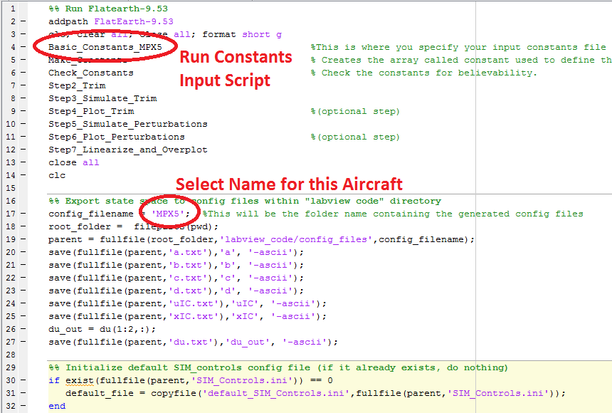
Step 1: Create FlatEarth constants input file
This is where you specify all the properties of your aircraft. FlatEarth will use these inputs to generate the state space that LabVIEW utilizes to run the simulation. Simflight comes packaged with 3 example constant input files: "Basic_Constants_MPX5.m", "Basic_Constants_PA_28_161_Warrior.m", "Basic_Constants_Albatross.m"
Step 2: Run FlatEarth to Simflight script
Locate the file: "FlatEarth_to_Simflight.m". This script wraps and runs the FlatEarth module to generate a state space. The resulting state space is exported into a set of text files that LabVIEW will parse at run-time. You must edit this script to properly identify and run the constants input file that you just created.
Step 3: (Optional) Modify SIM_Controls.INI
If the FlatEarth code ran successfully, you will have created a new folder in the config_files folder. It should look like this:

The newly created folder contains all of the text files (state space variables) required for the LabVIEW simulation. One file that you may wish to modify is the SIM_Controls.INI file. This files looks like this:
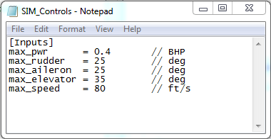
These numbers affect the range of motion of the joystick in the simulator. More specifically, if the max rudder is set at 25 degrees, then full rotation of the joystick yaw-axis will yield 25 degrees rudder deflection in the simulation. If you find that you want a more/less sensitive joystick, you can increase/decrease this number as you please. Simply edit the file and save. LabVIEW loads this file at run-time.
The max_speed input in slightly different. This simply affects the maximum number shown on the speedometer on the GUI.
Step 4: Run LabVIEW Simflight program
Locate and run the file: "Simflight.vi". Again, for this step, you will need both LabVIEW 2015 and the Control Design and Simulation Module installed. (Click the run-arrow in the menu-bar of the VI to start the program.)
Step 5: Specify SIM Inputs
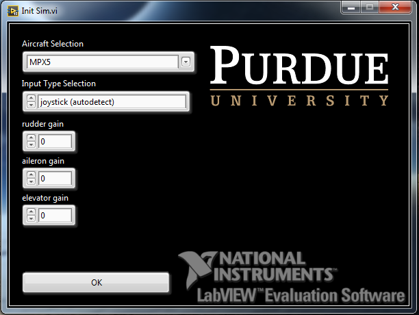
When the program is started, the user is promted for the following information:
- aircraft selection. Use the drop-down menu on this control to navigate the possible options. You should see your aircraft here if you ran the FlatEarth_to_Simflight.m script properly
- proportional feedback gains
- Control Input Source. (See below for more information about the various options here)
Step 5.1: joystick (autodetect) control option
This option will attempt to autodetect a Logitech Extreme 3D Pro joystick plugged into the computer. If successful, you'll be able to control the simulation in real-time with the joystick.
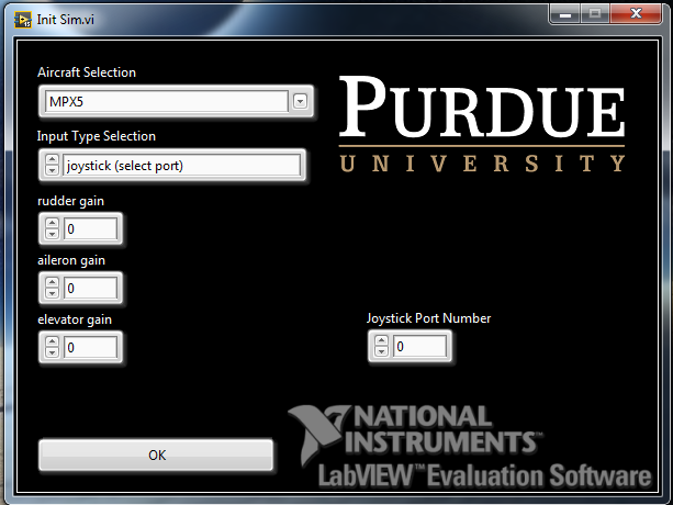
Step 5.2: joystick (select port) control option
If the auto-detect option isn't working, you can use this option to manually specify the port that your joystick is plugged into. This option might be useful for attempting to use the simulator with a different type of joystick. (Again, I can only guarantee compatibility with the Logitech Extreme 3D Pro joystick.) Use device manager to determine what port your joystick is plugged into.
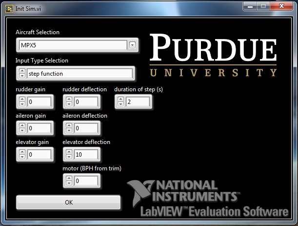
Step 5.3: step function control option
This option will apply a step-function to the state space. Note the following:
- duration of step
= how long the step input persists - rudder deflection = degrees of deflection from trim during step
- aileron deflection = degrees of aileron from trim during step
- elevator deflection = degrees of elevator from trim during step
- motor (BHP) from trip = throttle input from trim during step
You do not need a joystick for this method
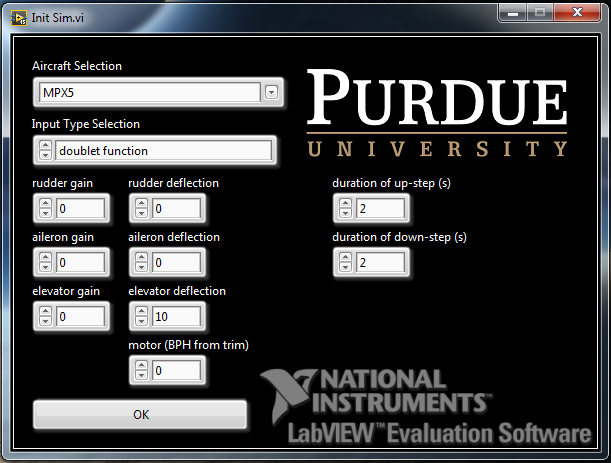
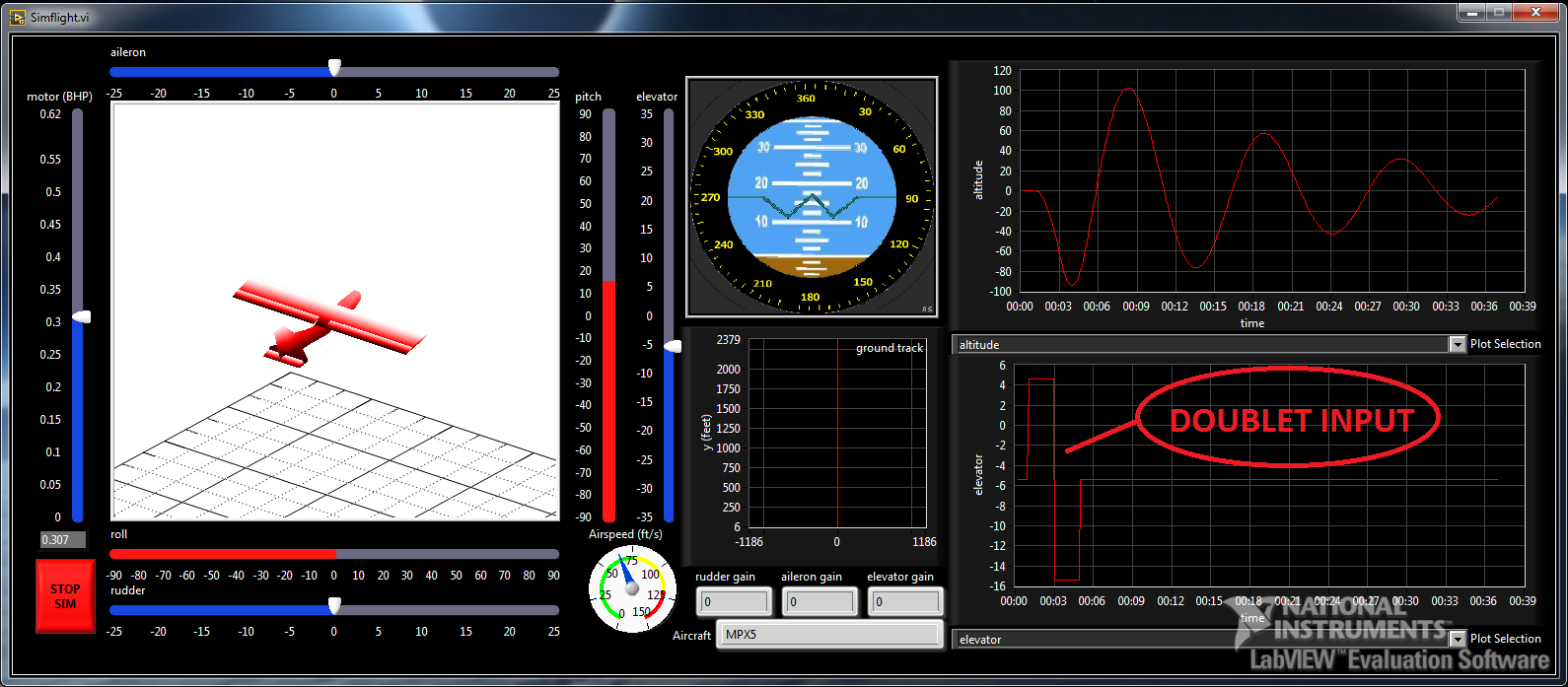
Step 5.4: doublet function control option
This option will apply a doublet-function to the state space. Note the following:
- duration of up step
= how long the positive step input persists - duration of down step
= how long the negative step input persists - rudder deflection = degrees of deflection from trim during step
- aileron deflection = degrees of aileron from trim during step
- elevator deflection = degrees of elevator from trim during step
- motor (BHP) from trip = throttle input from trim during step
You do not need a joystick for this method
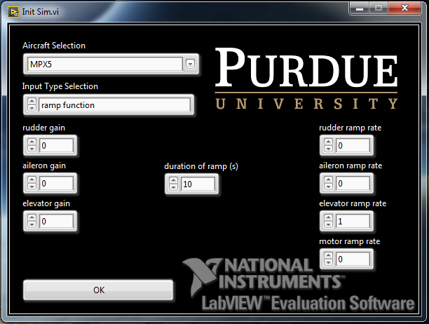
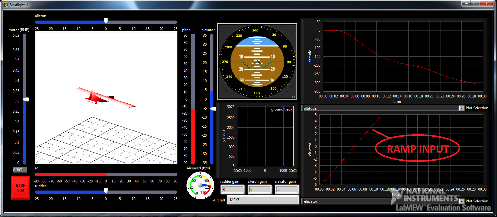
Step 5.5: ramp function control option
This option will apply a step-function to the state space. Note the following:
- duration of ramp
= how long the ramp input persists - rudder ramp rate= degrees/s of deflection from trim during the ramp
- aileron ramp rate= degrees/s of aileron from trim during the ramp
- elevator ramp rate= degrees/s of elevator from trim during the ramp
- motor ramp rate = BHP/s of throttle input from trim during the ramp
You do not need a joystick for this method
Data Analysis
The results of the simulation are automatically saved to a MATLAB data file (.mat) at the conclusion of the simulation. These data files can be found in the datalogs folder. It should look something like this after having run a few sims:
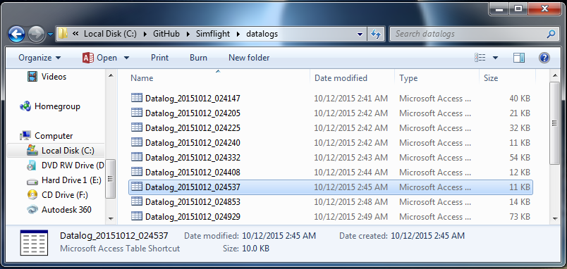
The filename is simply a timestamp of when the file was created at the end of the simulation. These files can be loaded directly into the MATLAB workspace using the "load" command. (These are simply Level-5 .mat variable files.)
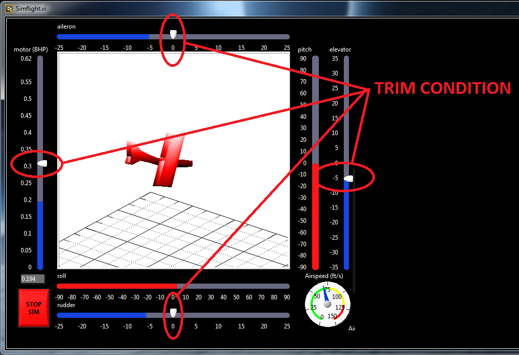
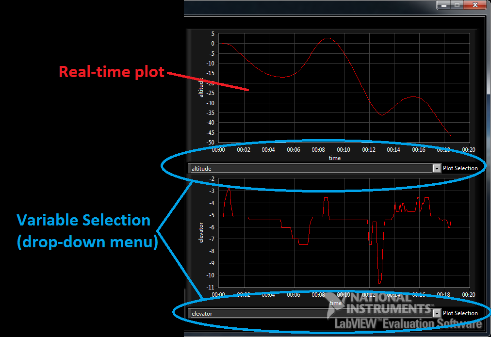
GUI Interface Description
The following images describe the GUI interface and the meaning/usefulness of various elements.
.png)
.png)
.png)
Simulation Validation
Simulation Validation - Longitudinal Direction
The longitudinal model was tested by injecting a doublet input on the elevator. More specifically, the elevator was deflected -1 degrees from trim for 1 second, then deflected +1 degrees from trim for 1 second, and then brought back to trim. The following figures show the FlatEarth output and Labview simulation output.
Figure 6: FlatEarth - pitch rate response to doublet elevator input
Figure 7: Labview simulation – pitch rate response to doublet elevator input
We see that the nonlinear FlatEarth, linear FlatEarth and Labview simulation results are all in acceptable agreement for pitch rate response to elevator commands. As such, the following can be concluded:
- Linearized model acceptable for near-trim flight
- Labview simulation model acceptably operating at real-time
We also see that with an elevator deflection, the pitch rate dampens out and approaches a steady state value of zero. This corresponds to a dynamically stable aircraft in the longitudinal direction. This observation is in agreement with the flight qualities analysis.
Simulation Validation - Lateral Direction
The lateral model was tested by injecting a doublet input on the aileron control. More specifically, the aileron was deflected +1 degrees from trim for 1 second, then deflected -1 degrees from trim for 1 second, and then brought back to trim. The following figures show the FlatEarth output and Labview simulation output.
Figure 8: FlatEarth - roll and yaw angle response to doublet aileron input
Figure 9: Labview simulation – roll and yaw angle response to doublet aileron input
We see that the nonlinear FlatEarth, linear FlatEarth and Labview simulation results are all in acceptable agreement for yaw angle and roll angle for approximately 7 seconds. After this time, the linearized solution begins to diverge from the nonlinear solution. This is to be expected as the linearized solution is only valid near trim conditions. At t=7 seconds, the aircraft is in a deep spiral dive - far from steady-level flight. We can conclude the following from these results:
- Linearized model acceptable for near-trim flight
- Labview simulation model acceptably operating at real-time
We also see from these figures that the aircraft is unstable in the lateral direction. As the aircraft rolls and yaws in one direction, the angle grows over time. This is in agreement with the flight quality analysis which found the aircraft to be unstable in the spiral mode.
Tutorial Video
Code Version Control:
The most recent code version can always be found at my GITHUB page:
Acknowledgements
1) Aircraft indicators taken from project here
2) Aircraft gimbal taken from project here
3) FlatEarth written by Professor Andriasani
Example code from the Example Code Exchange in the NI Community is licensed with the MIT license.
- Mark as Read
- Mark as New
- Bookmark
- Permalink
- Report to a Moderator
Great work! This is what the developers forum should showcase! Kudos
Certified TestStand Architect
Certified LabVIEW Architect
