Digital Output Multi Device Synchronization - Manual Routing
- Subscribe to RSS Feed
- Mark as New
- Mark as Read
- Bookmark
- Subscribe
- Printer Friendly Page
- Report to a Moderator
Code and Documents
Attachment
Overview
Usually DAQmx is smart enough to route signals through the backplane of a PXI chassis or over the RTSI lines on PCI devices, but there are some cases where DAQmx doesn't find a valid route and will throw an error. For these cases it is necessary to go into Measurement & Automation Explorer (MAX) to see what routes can be found and use the DAQmx Connect Terminals and DAQmx Disconnect Terminals functions to route the sample clock and triggers manually.
Description
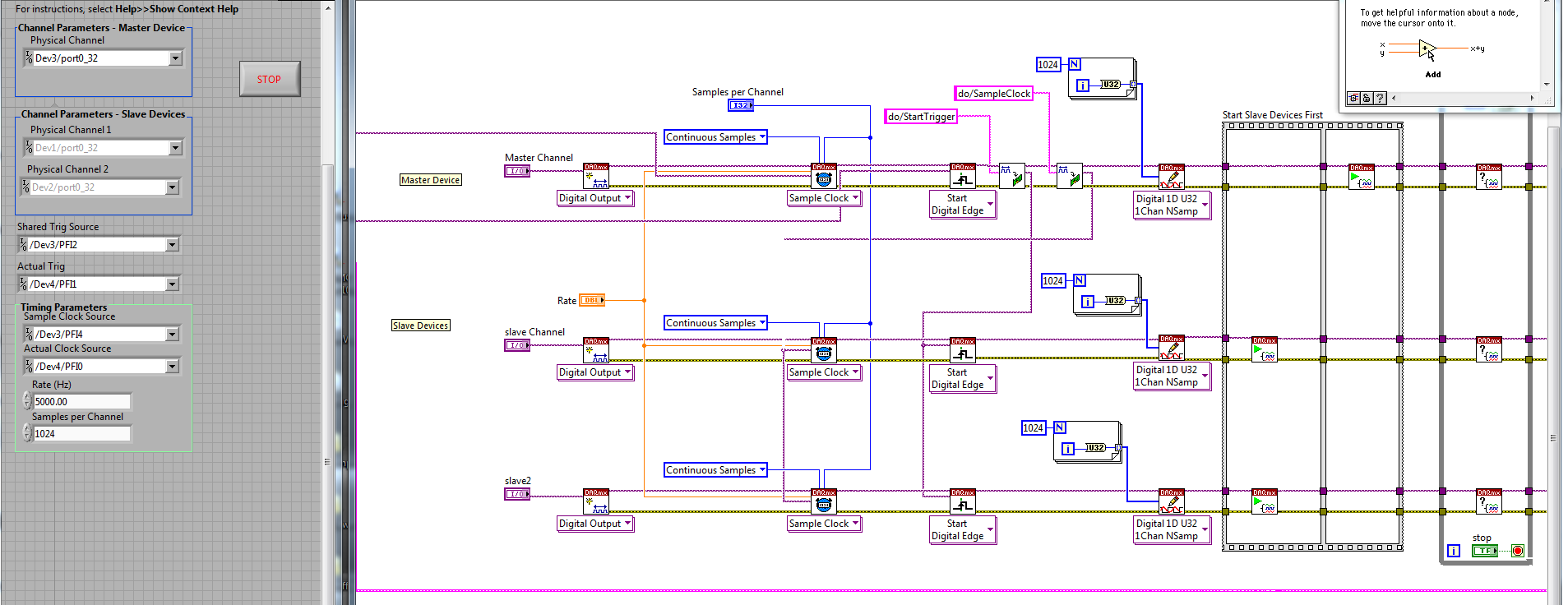
In this example, three PCI-6534 High Speed Digital IO cards are connected via RTSI cable and configured for Digital Output. In order to share a sample clock and start trigger, manual routing is necessary. First, the actual clock and shared sample clock terminals are connected and the actual trigger and shared trigger source terminals are connected. Next, the example proceeds like any other master-slave configuration making sure to start the slaves devices before the master device. After all tasks are cleared, the clock and trigger terminals are disconnected as we end with the Simple Error Handler.
Steps to Implement or Execute Code
- Download and unzip files
- Configure the Get Terminal Name and Device Prefix subVI
- Configure the parameters for the shared trigger and clock sources
- Run
Requirements
Software
LabVIEW 2009 or later
DAQmx
Hardware
This example was designed with PCI 6534 HSDIO devices, but any DAQmx digital device should work as well.
VI Snippet
Staff Software Engineer
National Instruments
Example code from the Example Code Exchange in the NI Community is licensed with the MIT license.
