Emitting Audio Frequencies on Command with NI DAQ Devices
- Subscribe to RSS Feed
- Mark as New
- Mark as Read
- Bookmark
- Subscribe
- Printer Friendly Page
- Report to a Moderator
Products and Environment
This section reflects the products and operating system used to create the example.To download NI software, including the products shown below, visit ni.com/downloads.
- Multifunction I/O Device
Hardware
- LabVIEW
- LabWindows/CVI
- Measurement Studio
Software
- NI-DAQmx
Driver
- C
- C Sharp
- C++
- Visual Basic .NET
Programming Language
Code and Documents
Attachment
Description
Description-Separate-1You depend on measurements to make key decisions and discoveries. NI offers a wide range of data acquisition products, including the low-cost DAQ family for basic applications such as simple data logging, portable measurements, and academic lab experiments. Choose the right high-quality hardware based on the requirements for your application and budget.
Take advantage of free NI resources to help you get to your measurement faster. In this tutorial, modify one of the hundreds of measurement-specific examples included with your device to learn how to build a basic application that emits an audio frequency when you press a button. NI low-cost DAQ products feature a variety of devices ideal for this type of basic application. For this tutorial, we work with the NI USB-6003 because it features hardware-timed audio output, which prevents distortion in the audio frequency. However, you can apply this code to any NI DAQ device that has digital input and hardware-timed analog output capabilities.
These devices come with software support for ANSI C, Visual C++, C# .NET, Visual Basic .NET, NI LabVIEW, NI LabWindows™/CVI, and NI Measurement Studio as well as configuration software. We demonstrate the task using LabVIEW, but you can complete this same task in other application development environments or programming languages. To see tutorials for other programming languages such as ANSI C or C# .NET, select from the tutorials linked at the bottom of the page.
How to Use
How-Separate-1What You Need
Hardware
- NI multifunction DAQ device (this tutorial uses USB-6003)
- Push button
- Speaker
- Headphone jack
- Wires
Software
- LabVIEW
- NI-DAQmx driver version that supports your device (the USB-6003 requires NI-DAQmx 9.9 or later)
Hardware Instructions
Setting Up the Device
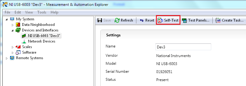
First, make sure you have installed the supporting NI-DAQmx driver software version. If you are using a USB DAQ device, a green or blue LED light should turn on when the device is recognized by your host PC. Open Measurement & Automation Explorer and confirm that the device appears under Devices and Interfaces. Select the Self-Test button and confirm that the device passes.
Connecting the Push Button
The push button should have two terminals. Connect one of the terminals to P2.0 and connect the second terminal to 5 V.
Connecting the Speaker
This tutorial uses a speaker plugged into a two conductor (mono) phone jack. Two wires were soldered to the two terminals and one connected to ground, another to AO0, according to the diagram on the phone jack. Follow the diagram on your phone jack to connect the terminals to the analog output channel and ground.
Software Instructions
Map Your Program Flow and Start With an Example
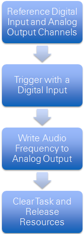
For our application, we want to emit an audio frequency on command. To do this, we set up a program that creates and configures a physical digital input and analog output channel, waits for a digital trigger to occur, and then writes a frequency to the speaker. When we are done emitting the frequency, we want to be able to stop the program, clear the tasks, and release the resources. The basic flow of the program is in the following diagram.
Instead of building this entire application, we’re going to use one of the example programs included with your DAQ device. You can find the location of these example programs for your specific OS by visiting ni.com/info and typing in daqmxexp. We are going to modify a LabVIEW voltage output example called Voltage – Continuous Output.vi, which demonstrates how to continuously regenerate analog output data that is configured by the user. This example also incorporates digital triggering, so we do not have to add this to our code.
Copying the Example Program Into Your Personal Folder
Copy the example program from its original location into your personal folder, so that modifications to your program do not overwrite the original example.
Opening the Program
The first thing that you should notice in your program is the comments that designate sections of the code. In this example, there are five sections in the code: Channel Settings, Timing Settings, Trigger Settings, Waveform Settings, and Output. Documenting your code as you make changes is a best practice that allows your code to be read and understood.
Modifying the Code
Follow these steps to modify the example or open the finished program attached to this tutorial.
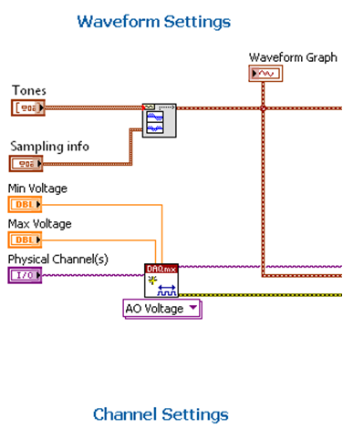
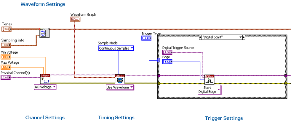
- Add the Tones and Noise Waveform.vi to the block diagram above the DAQmx Create Channel.vi. You can find the Tones and Noise Waveform.vi in the Programming»Waveform»Analog Waveform»Generation palette. Right-click the Tones and Sampling info Nodes and select Create»Control. This gives the user the ability to modify these parameters on the front panel before running the code. Double-click the graph on the front panel to locate it on the block diagram. Break the current connections and connect the terminal to the Signal Out node of the Tones and Noise Waveform.vi. Label this section of code "Waveform Settings". Your code should look like the following:
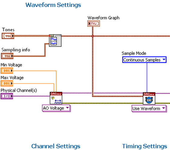
- Change the DAQmx Timing.vi from Sample Clock to Use Waveform. Remove the Sample Rate and Sample Clock Source terminals and the broken wire. Keep the sample mode as Continuous Samples. Wire the waveform output from the Tones and Noise Waveform.vi into the waveform input. By using waveform input instead of sample clock, you configure your timing settings to match the frequency of the waveform that we want to generate. Your code should look like the following:
- Remove the DAQmx Timing Property Node and the Actual Sample Rate output.
- Keep the trigger settings as the default, because it gives us a digital trigger option that we can configure in our user interface (UI) to use the push button as the trigger. Your code should look like the following:
- Remove the following code. We are using the Tones and Noise Waveform.vi to produce the audio frequency instead of the Basic Function Generator used in the original example.
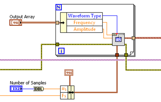
- Wire the waveform output from the Tones and Noise Waveform.vi to the data input of the DAQmx Write.vi. Leave the Output code. Your code should look like the following:

Modifying the UI
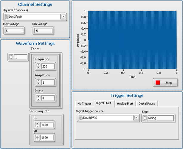
- Under Channel Settings, specify the name of the device and analog output channel you are using. In this tutorial, our device is named Dev3 and we are using analog output channel 0. Keep the default voltage values.
- Under Trigger Settings, select Digital Start, configure the Trigger Source to be /Dev3/PFI0, and trigger off of a rising edge. This will allow us to use the push button to emit the audio frequency.
- Drag the Tones and Sampling info cluster into the Waveform Settings section of the UI. Adjust the Frequency to 250 Hz, the Amplitude to 1 and the Phase to 0. The frequency controls the audio tone whereas the amplitude controls volume. The amplitude should be set to no more than 1 for most speakers, as higher inputs could potentially damage speakers. Start with the volume on the speakers turned all the way down and slowly turn up for desired volume. The phase specifies the initial phase of the sine tone in degrees. The default is 0.
- For Sampling info, leave the default sampling rate and number of samples in the waveform as 1000. You UI should look like the following:
Running Your Program
To run the program, select the run arrow. Compress the push button and hear an audio tone emitted from your speakers. Select Stop on the UI to stop the program.
The mark LabWindows is used under a license from Microsoft Corporation. Windows is a registered trademark of Microsoft Corporation in the United States and other countries.
Related Links
Related-Separate-1- NI Low-Cost, Multifunction DAQ Devices
- USB-6003
- Learn 10 Functions in NI-DAQmx and Handle 80 Percent of Your Data Acquisition Applications
Example code from the Example Code Exchange in the NI Community is licensed with the MIT license.
