Passing External Clock Through DIO And Dividing External Clock
- Subscribe to RSS Feed
- Mark as New
- Mark as Read
- Bookmark
- Subscribe
- Printer Friendly Page
- Report to a Moderator
Code and Documents
Attachment
Overview
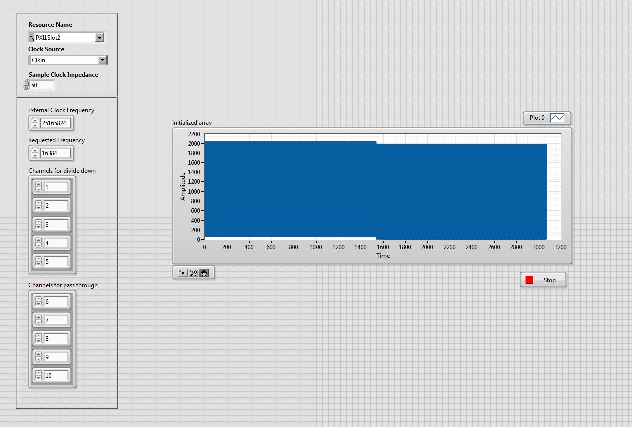
This VI takes in an external clock (through clock in) on the HSDIO module. It then allows the user to choose which digital output they would like to pass the clock through to and which outputs they would like the divided clock to go to. The user can also select what clock they would like to dervive from the external clock. The VI programmatically generates the patterns needed for HSDIO cards.
Description
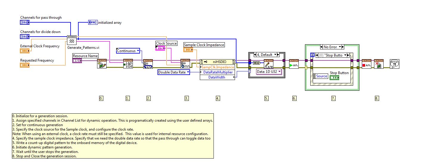
When using the HSDIO modules, you cannot simply write an array of booleans to the "Write Named Waveforms.vi". You have to reference all the channels at once. For example, if you would like to turn on only DIO2 (remember they are 0 index) then you would need to write a binary value of 100b or 4 in decimal. This VI creates the patterns needed to reference the DIO lines. It should be noted that becasue we want some lines to simply pass the external clock through, we need to use double data rate. The reason for this is so that we clock on the rising and falling edges of the signal - if we don't do this then we will divide the clock by two.
Steps to Implement or Execute Code
- Open the DDR and Divided Clock Project
- Open the DDR and Divided Clock.vi
- Set your HSDIO card in the 'Resource Name' and your 'Sample Clock Impedance', and finally 'Clock Source'.
- Set your external clock and what you would like it to be divided down too.
- Lastly, set which lines you want the divided clock to go to and which ones you want the external clock to pass straight through
Requirements
Software
Tested with LabVIEW 2013
HSDIO Drivers
Hardware
HSDIO Card
Additional Images or Video
Example code from the Example Code Exchange in the NI Community is licensed with the MIT license.
