Transferring multiple channels of data through a single communication link
- Subscribe to RSS Feed
- Mark as New
- Mark as Read
- Bookmark
- Subscribe
- Printer Friendly Page
- Report to a Moderator
Code and Documents
Attachment
Introduction
In a lot of scenarios, you may find it neccessary to send multiple channels of data between two devices or applications. However, sometimes you are limited to having just a single channel. For example, imagine you have a CompactRIO, and the FPGA controls five separate motors, whilst the Host VI generates five seperate sets of positions for these motors. How can you send these five seperate data sets to the FPGA VI. The obvious answer would be to use five FIFOs, however most CompactRIOs only have three DMA FIFOs that can be used. Also, for synchronising motors, it can be very beneficial to have all five sets of positions sent through a single channel. How can you achieve this?
Note - This example is geared towards sending data from a Real Time VI to an FPGA VI using a single FIFO. However the encoding and decoding schemes in the attached code can be used for any situation in which multiple channels of data need to be send through a single communication link. Other examples could include transmitting data using an XBEE radio, or sending serial data using various protocals like I2C or SPI.
Description
There are multiple methods of achieving multi-channel data down a single link, this example shows the method of encoding data into a single datapoint so that it can be sent down a FIFO. Other methods include interleaving the data (A good example of that is here), or sending header packets.
In this example we will be sending I32 data. If we are sending data for multiple channels through a single link, then each datapoint sent must have a 'Value' and 'Associated Channel'. In the previous example for motors, the 'Value' could be a specific position, and the 'Channel' could be which specific motor the position should be applied to. To combine the 'Value' and 'Channel' information into a single datapoint to be sent, we must split the datapoint into separate parts.
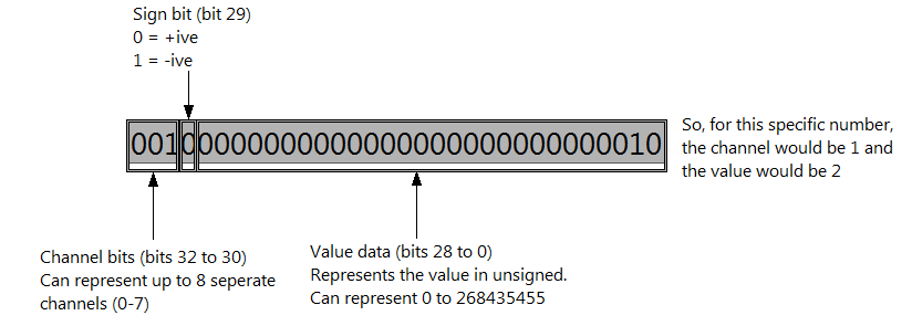
In this example, we use the three left-most bits (bits 32 to 30) in the I32 to store information for the channel, we use bit 29 to store the sign of the value (+ or -) and we use the remaining 28 bits to store the actual value. The picture below illustrates how a single I32 is split up in this scheme.
On the host side, the 'Value' and 'Channel' data can be encoded into this single I32.
This coded I32 can then be sent as a single datapoint through the communication channel.
Once on the target, the datapoint can be decoded, and the 'Value' can be written to whichever specific 'Channel' it was intended for.
In the motor control example, we could use the 'Channel' information to decide which motor to write the 'Value' (position) to.
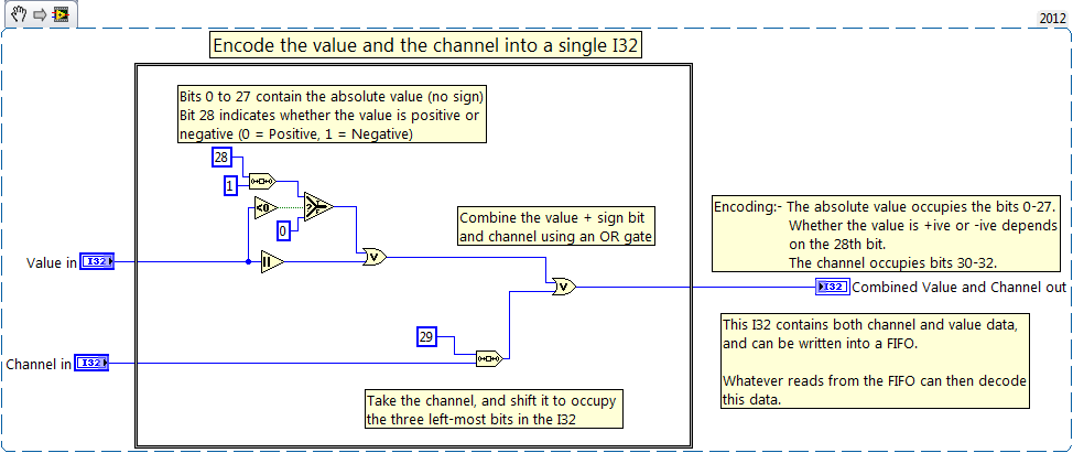
The picture below shows how the 'Value' and 'Channel' information is encoded into an I32.
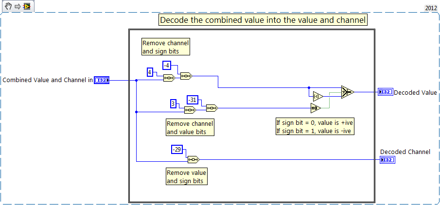
Once encoded, it can be send down a communication channel, and decoded using the code shown below.
You don't have to have a full understanding of exactly what's going on to the bits here, but I've tried to annotate the steps in case you wish to follow through what's happened to encode/decode the information.
One thing to watch out for if you're using this -
Only 28 bits are used for the value, the 29th bit is used for the sign. This means the value you send must be between -268435455 and +268435455. Also, only three bits are used for the channel, so you can only have 0-7 channels. That said, it shouldn't be too hard to edit this code to change the lengths used for these values, or even to get the code to send I64 data.
Applications Engineer
National Instruments UK & Ireland
Example code from the Example Code Exchange in the NI Community is licensed with the MIT license.
