ni.com is experiencing intermittent service disruptions.
Support teams are actively working on the resolution.
ni.com is experiencing intermittent service disruptions.
Support teams are actively working on the resolution.
Overview
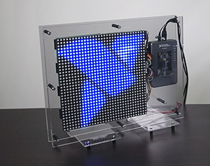
myRIO LED wall is a 32x32 RGB LED matrix controlled by National Instruments myRIO. This project utilised the myRIOs onboard FPGA chip, and as a result the LED matrix was able to display images, display a webcam input and even play games, such as Snake and Flappy bird!
Principle of Operation
How to control a large LED array?
Having direct control over the every LED by dedicating a digital line for it. But 32x32 LED matrix has 1024 cells, each cell has 3 LEDs (Red, Green, Blue), so in total we have to control 1024x3 = 3072 LEDs. Imagine the amount of wiring it would require and at the moment it is impossible to find a controller with 3072 digital channels, making this solution highly impractical.
However having control over the Rows and Columns gives us the ability to address every LED of the matrix, just by activating a specific Row and Column. The downside of this method is that only one row of the LED matrix can be activated at one time. It happens because we have to share LED anodes ( + ) to control rows and cathodes ( - ) to control columns.
To give the appearance of a regular screen, where all the LEDs are active at once, fast switching (multiplexing) between rows is required, turning the corresponding columns ON and OFF. If multiplexing is not quick enough the "flickering" effect may become more apparent.
Hardware
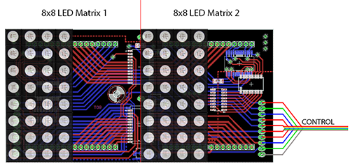
The LED matrix consists of 8 PCBs, each holds two small 8x8 RGB LED matrices.
A custom PCB has been designed and manufactured for this project (you can find the schematic in the attachment).
Each cell contains 3 LEDs (Red, Green, Blue😞
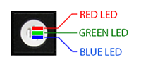
Mixing different shades of LEDs allows to produce any color. Each LED has 255 shades. As a result the total number of color combinations is 255x255x255 = 16.5 million. Shades are controlled using the Pulse Width Modulation (PWM) technique to control how much power flows into the LED. The more power the LED receives the brighter it is, the less power it receives the dimmer it is.
In this project 8 PCBs were stacked together to increase the size of the matrix:
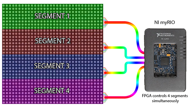
In order to minize the "flickering" effect, the screen is divided into 4 segments (separate 8x32 screens) which are controlled by the NI myRIO simultaneously utilising the powerful onboard FPGA chip for a very fast and deterministic execution.
Applications
1. Image Gallery - simply displays any 32x32 image.
2. Screen Capture - takes a small region of 32x32 around the cursor and displays it.
Code: Community: Continuous screen capture example in LabVIEW
3. Play video - plays any video file.
4. Snake Game - simple snake game implemented in LabVIEW.
Code: Community: Snake game in LabVIEW
5. Conway's Game of Life - famous zero-player game.
6. WebCAM - takes a stream from the camera and displays it on the screen.
Code: Community: Video to LED matrix display converter
Video
Example code from the Example Code Exchange in the NI Community is licensed with the MIT license.
Good day
My name is leon I have build a 8x8x8 led cube using an ARDUINO and a self made curcuitboard that acts like a multiplexand the cube thats running on C+. However is there away that i can convert it to labview
Thank you very much for your help.
Leon for Miami Dade College/robotics club
Dear Leon,
Thank you for your question. There is no automated way to convert the C++ code
into the LabVIEW. Since you made an LED Cube and programmed it, you should
be able to replicate exactly the same code in LabVIEW. Try to do it step by step
(e.g. turn on 1 LED first, then 1 row, then full cube). I am sure that you will be fine.
Please let me know if you need help with LabVIEW coding.
Kind Regards,
Max
Hi there
Thank you very much for your reply and i will keep you posted..
Regards
Leon
Hello
Can you instruct me how to wire the LEDS to my rio?
Thanks in advance
Hi BaZ418,
As I understand about your question that is how to control LEDs by using MyRIO and LabVIEW Tool? Am I right?
Hi M.Kuznetsov,
I would like to ask you that have you ever using LabVIEW to design your own application without using NI component such as MyRIO? For example with the microcontroller such as 8051, PIC, AVR, ARM, and Arduino?
Hi can you tell me the name of webcam used in project? it very nice
that's right, ic1 & ic2 is not given, even the ckt for led over the board is not given or am missing it!
Hello
can i control the color and intensity of rgb led at the same time? emmm...i only have myRIO and some rgb leds.
