- Subscribe to RSS Feed
- Mark Topic as New
- Mark Topic as Read
- Float this Topic for Current User
- Bookmark
- Subscribe
- Mute
- Printer Friendly Page
We are going to change the Channel wire appearance
08-31-2015 10:27 AM
- Mark as New
- Bookmark
- Subscribe
- Mute
- Subscribe to RSS Feed
- Permalink
- Report to a Moderator
AristosQueue wrote:
Your specific objections include...? 🙂
No objections. Like I said, I just don't grok it properly. When I see such code I don't say "oh, that's what it represents". Instead, I'm just confused. That was why I made that simple example, but even that didn't help.
Maybe I would understand it better after using it in real code. Maybe not. So far, I don't get it. I expect the main reason I don't get it is that it looks like it's created in one place, but it's actually created somewhere else. Maybe adorning each channel with a glyph at the creation point would help, essentially providing a different visual element to the green wire wrapper (which I never actually saw).
I think I would get it if it was clear that this was a system diagram (e.g. if the nodes represented different hardware targets), and that's why I gave the subVIs in my second image a while loop icon, but that still looks too much like dataflow to me.
So far I have no opinion on whether or not LV should have this. My natural inclication is for LV to have it, because even if I won't use it and it might be hard to understand, others might want to use it, but that's because I tend to live and let live.
___________________
Try to take over the world!
08-31-2015 10:40 AM
- Mark as New
- Bookmark
- Subscribe
- Mute
- Subscribe to RSS Feed
- Permalink
- Report to a Moderator
tst wrote:
essentially providing a different visual element to the green wire wrapper (which I never actually saw).
You need to put a config token in your config file to see the green wire. The token is in the Read This First page.
tst wrote:
I think I would get it if it was clear that this was a system diagram (e.g. if the nodes represented different hardware targets),
That's actually what we're trying to avoid. We do not want this to be restricted only to a different model of computation. This is intended for use on the regular G diagrams. Yes, we want it to span targets someday, but having to have a separate diagram to express the commuication results in needing a refnum wire on the actual sender/receiver diagrams. Not nearly as clean and definitely not as syntax checkable for purposes of verification and validation.
09-04-2015 05:41 AM
- Mark as New
- Bookmark
- Subscribe
- Mute
- Subscribe to RSS Feed
- Permalink
- Report to a Moderator
Mmmmh... Honnestly, I love this Channel concept, but I also tend to prefer the more 3D, round wire aspect of the released version. The round wire are totally distinct from other wires, at least much more than what you propose, as nicely illustrated by Thoric... They are more easily identified at first glance as "non regular, non-data-flow wire" than the new design, to my opinion. And identifying what is data-flow and what is channel looks much more important to me than knowing the underlying data type to me, at least at first glance when debugging a VI.
But now if you tell us they cannot be supported with the current graphical environment, there's not much we can do about that...
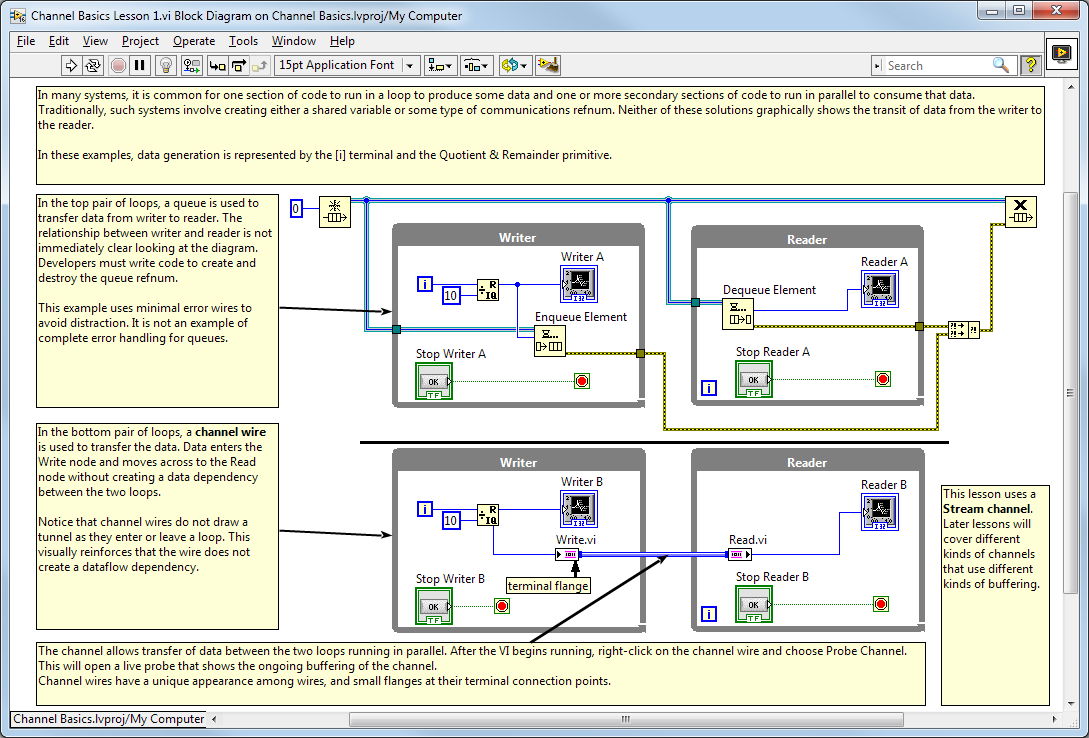
Actually, when looking at examples (I haven't used them in a real project yet), the most "visual" aspect is the lack of tunnels through structure borders. This is just GREAT and tells us all. Very intuitive : this is definitely not data flow.
HOWEVER, this is lost when using subVIs. Will I really always correctly identify which wires are Channels in a diagram with many interconnected subVIs ?
Therefore my suggestion : could this be solved by introducing a "signature" for channel wires on the connector side ? Just like coercion dots... Either on the border of (but within) the icon, or on the first few pixels of the channel wire itself ? A quick and dirty example with 2 different suggestions :
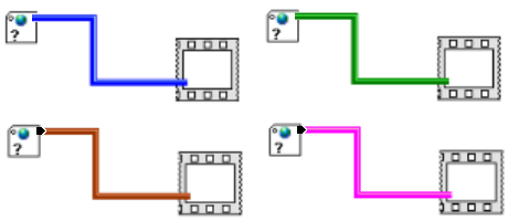
After all, discriminating between data-flow and channels only matters when looking at an executable piece of diagram (structure, subVI) to answer the question : when will this be executed. Wires as such are not "executed", and I don't need to identify a channel wire type along all its length, I just need an easy way to follow its path through the diagram to see where it is going to...
Vincent
09-04-2015 09:37 AM
- Mark as New
- Bookmark
- Subscribe
- Mute
- Subscribe to RSS Feed
- Permalink
- Report to a Moderator
Vincent: That's an interesting ponit. I'll raise it with the team.
10-09-2015 02:38 PM
- Mark as New
- Bookmark
- Subscribe
- Mute
- Subscribe to RSS Feed
- Permalink
- Report to a Moderator
I agree with the last comment, that a graphical element at the connection point would very clearly distinguish the Channel from a normal wire and could give a visual indication of it's relationship within the diagram.
Personally, I picture the Channel coming "out of" and back "into" the block diagram, as if there were another layer above the surface of the monitor.
In/out arrows (circled dot and circled crosshair) or a simpler graphic that represents a riser would fit how I see it.
That's my 2cents, perhaps worth half that. 
10-12-2015 03:24 PM
- Mark as New
- Bookmark
- Subscribe
- Mute
- Subscribe to RSS Feed
- Permalink
- Report to a Moderator
It's been a while since I updated this thread. We took a look at Vincent's comments and some other feedback we got elsewhere. Here's where we've ended up... this is a screenshot of one of the new shipping examples. You can see the small flanges sticking out from the nodes. We decided against going into the heart of the node in favor of a different shaped outside of the terminal.
10-13-2015 02:10 AM
- Mark as New
- Bookmark
- Subscribe
- Mute
- Subscribe to RSS Feed
- Permalink
- Report to a Moderator
Excellent, I love it ! I think this makes it quite clear it's not a standard wire obeying the good old dataflow paradigm - no more protests about breaking it I hope...
And now I can pretend I'm a real plumber while wiring a diagram - oh, and if your code starts to misbehave after a couple of years, first check you don't have any leak around that pipe flange, it might be time to change the seal 
12-08-2015 01:44 PM
- Mark as New
- Bookmark
- Subscribe
- Mute
- Subscribe to RSS Feed
- Permalink
- Report to a Moderator
Is it possible to get a legible screenshot of "one of the new shipping examples"? I have no idea what I am looking at.
12-08-2015 02:20 PM
- Mark as New
- Bookmark
- Subscribe
- Mute
- Subscribe to RSS Feed
- Permalink
- Report to a Moderator
Click on the screen shot and it should open in full resolution. It does move off to the side so you need a wide monitor to see it.
12-09-2015 01:27 AM
- Mark as New
- Bookmark
- Subscribe
- Mute
- Subscribe to RSS Feed
- Permalink
- Report to a Moderator
I Like it, Holger
