- Subscribe to RSS Feed
- Mark Topic as New
- Mark Topic as Read
- Float this Topic for Current User
- Bookmark
- Subscribe
- Mute
- Printer Friendly Page
ADXL 345 Sparkfun-- I2c--LabVIEW--Arduino
05-19-2013 07:55 AM
- Mark as New
- Bookmark
- Subscribe
- Mute
- Subscribe to RSS Feed
- Permalink
- Report to a Moderator
Hi Nathan,
while using single ADXL345 everything was working, but when I try with couple I am getting the data (getting 0 for all axis and just one accel while reading with serial monitor)
Here is my code with connection detail (I am using Arduino with ADXL345 with breakout board)
// Cabling for i2c using Sparkfun breakout with an Arduino Uno / Duemilanove:
// Arduino <-> Breakout board
//Accell - 1 (0x53)
// Gnd - GND
// 3.3v - VCC
// 3.3v - CS
// Analog 4 - SDA
// Analog 5 - SLC
//Accell - 2 (0x1D)
// Gnd - GND
// 3.3v - VCC
// 3.3v - CS
// Analog 2 - SDA
// Analog 3 - SLC
#include <Wire.h>
#define DEVICE (0x53) // Device address as specified in data sheet
#define DEVICE (0x1D) // Device address as specified in data sheet
byte _buff[6];
char POWER_CTL = 0x2D; //Power Control Register
char DATA_FORMAT = 0x31;
char DATAX0 = 0x32; //X-Axis Data 0
char DATAX1 = 0x33; //X-Axis Data 1
char DATAY0 = 0x34; //Y-Axis Data 0
char DATAY1 = 0x35; //Y-Axis Data 1
char DATAZ0 = 0x36; //Z-Axis Data 0
char DATAZ1 = 0x37; //Z-Axis Data 1
void setup()
{
Wire.begin(); // join i2c bus (address optional for master)
Serial.begin(19200); // start serial for output. Make sure you set your Serial Monitor to the same!
Serial.print("init");
//Put the ADXL345 into +/- 4G range by writing the value 0x01 to the DATA_FORMAT register.
writeTo(DATA_FORMAT, 0x01);
//Put the ADXL345 into Measurement Mode by writing 0x08 to the POWER_CTL register.
writeTo(POWER_CTL, 0x08);
}
void loop()
{
readAccel(); // read the x/y/z tilt
delay(500); // only read every 0,5 seconds
}
void readAccel() {
uint8_t howManyBytesToRead = 6;
readFrom( DATAX0, howManyBytesToRead, _buff); //read the acceleration data from the ADXL345
// each axis reading comes in 10 bit resolution, ie 2 bytes. Least Significat Byte first!!
// thus we are converting both bytes in to one int
int x = (((int)_buff[1]) << 😎 | _buff[0];
int y = (((int)_buff[3]) << 😎 | _buff[2];
int z = (((int)_buff[5]) << 😎 | _buff[4];
Serial.print("x: ");
Serial.print( x );
Serial.print(" y: ");
Serial.print( y );
Serial.print(" z: ");
Serial.println( z );
}
void writeTo(byte address, byte val) {
Wire.beginTransmission(DEVICE); // start transmission to device
Wire.write(address); // send register address
Wire.write(val); // send value to write
Wire.endTransmission(); // end transmission
}
// Reads num bytes starting from address register on device in to _buff array
void readFrom(byte address, int num, byte _buff[]) {
Wire.beginTransmission(DEVICE); // start transmission to device
Wire.write(address); // sends address to read from
Wire.endTransmission(); // end transmission
Wire.beginTransmission(DEVICE); // start transmission to device
Wire.requestFrom(DEVICE, num); // request 6 bytes from device
int i = 0;
while(Wire.available()) // device may send less than requested (abnormal)
{
_buff = Wire.read(); // receive a byte
i++;
}
Wire.endTransmission(); // end transmission
}
Please let me know what I am missing. I have not tried using VI with single accell via I2C yet, but I am going to try it now.
Thank you!
05-19-2013 10:12 AM
- Mark as New
- Bookmark
- Subscribe
- Mute
- Subscribe to RSS Feed
- Permalink
- Report to a Moderator
hello working with the same accelerometer, you attach a demo program
05-27-2013 12:32 AM
- Mark as New
- Bookmark
- Subscribe
- Mute
- Subscribe to RSS Feed
- Permalink
- Report to a Moderator
srajasek wrote:
Please let me know what I am missing. I have not tried using VI with single accell via I2C yet, but I am going to try it now.
Thank you!
Post after you have tried it with the LIFA library (also a link to the version that you are using).
06-28-2013 05:05 PM
- Mark as New
- Bookmark
- Subscribe
- Mute
- Subscribe to RSS Feed
- Permalink
- Report to a Moderator
Hi guys, this thread is old, but I'm hoping someone is still out there! I've loaded Sambo's VI into labview, everything looks good, but nothing works. I'm brand new to this though and I can't figure out what to do with the library etc. I know the adxl345 is working, the Arduino software Serial Monitor proves that. Can I not run the VI on it's own? Is there some requirement of LabView to incorporate the library?
Sorry if these are utter noob questions, but that's pretty much what I am lol
Thanks in advance if someone gets this!
G
06-28-2013 10:27 PM
- Mark as New
- Bookmark
- Subscribe
- Mute
- Subscribe to RSS Feed
- Permalink
- Report to a Moderator
G031,
You should use the library posted here (There are no difference between Sambo's and mine).
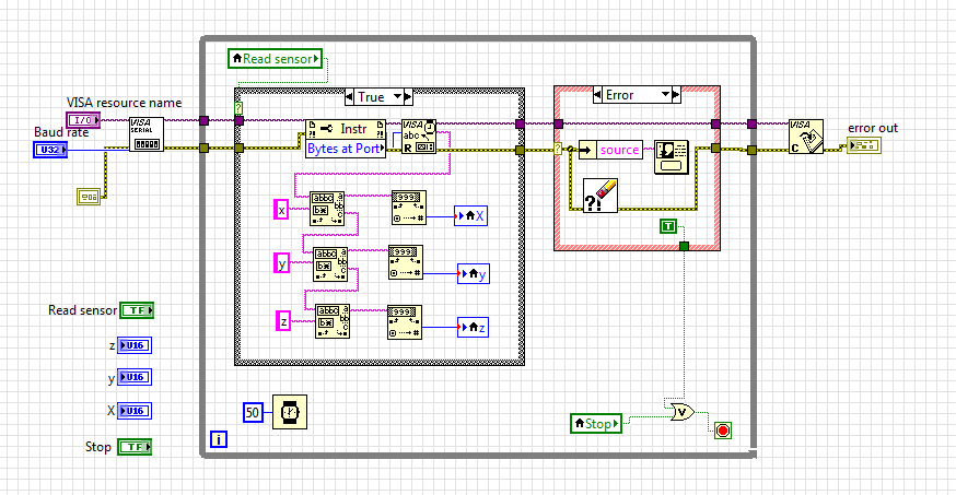
The first step is to open the "LIFA ADXL345.lvlib" file by double clicking on it. In this newly opened window, you should open the "Read Axes.vi" in the examples folder. If you are using an Arduino Uno, nothing on the block diagram should need to be changed (this assumes that you have already been able to run the Blink example). Simply run it.
Once you have that working, you can then create your own VIs using the VIs provided in the library. To do this, you can either drag the VIs from another VI (such as the example) to your new or existing VI OR you can drag the VIs directly from the library's window onto your block diagram.
If you have any specific questions or issues with the ADXL345 Library, please feel free to post in a reply in the document.
07-02-2013 12:55 PM
- Mark as New
- Bookmark
- Subscribe
- Mute
- Subscribe to RSS Feed
- Permalink
- Report to a Moderator
Thank you for the info Nathan, for some reason it reports random numbers, 10,0,0 then it starts flashing back and forth between those and rediculous numbers 8XXX,10XXX,11XXX (or so...) then it posts a timeout error... The code looks great, I cannot find anything that would indicate why this won't work.
07-05-2013 03:33 PM
- Mark as New
- Bookmark
- Subscribe
- Mute
- Subscribe to RSS Feed
- Permalink
- Report to a Moderator
I don't think these are what you are looking for? The LIFA base is just the file provided as a download from NI and the LIFA ADXL345 is from your library... If you mean the code I'm using to confirm that the adxl345 is working then it's the third file listed- 3Daccel. I don't have it outputting to Labview (I've not gotten that to happen successfully, in any way, so far), just watching the numbers scrolling by using the built in "serial monitor" in the Arduino base program.
07-06-2013 01:57 AM
- Mark as New
- Bookmark
- Subscribe
- Mute
- Subscribe to RSS Feed
- Permalink
- Report to a Moderator
G031, are you only using the example? If no, then please post the VI that you are using (your main VI, not my library).
EDIT:
From the 3Daccel.ino, the first thing that I noticed is that it sets the power register (0x2D) to three different values. Not sure if this is relevant since it just overwrites the previous value. I'm guessing it's not significant.
The second and likely most important thing that I notice (with regard to a difference to the Arduino code and the LIFA Example I created) is that the default device address is not the same as the address used in your Arduino code. So, make sure you have the correct device address input into the ADXL345 VIs.
I would suggest only changing the device address in the example and trying it that way first. If this doesn't work, you can try adding those three register writes to the LabVIEW code to see if that helps.
07-08-2013 01:59 PM
- Mark as New
- Bookmark
- Subscribe
- Mute
- Subscribe to RSS Feed
- Permalink
- Report to a Moderator
I was hoping to get something to work (your example) before commiting the time to building my own. Proof of concept, as it were.
There is\seems to be, a requirement to communicate with the unit that way- from Live Fast Code Young- "We first reset the power control register, then put the sensor in standby mode, and last we are putting it in to measure mode. We're doing the writes one after another because that's what the datasheet recommends. We could simply do the last write also" (http://codeyoung.blogspot.ca/2009/11/adxl345-accelerometer-breakout-board.html) (credit where it's due).
I have been switching the device address to match the way I've wired my unit, 0x53, but I'll switch it up hold the SDO high, instead of grounding, to utilize the 0x1D address to match your program like you've suggested, perhaps that'll sort something out.
I'll try this out and get back to you!
07-08-2013 03:37 PM
- Mark as New
- Bookmark
- Subscribe
- Mute
- Subscribe to RSS Feed
- Permalink
- Report to a Moderator
The datasheet says "When clearing the AUTO_SLEEP bit, it is recommended that the part be placed into standby mode and then set back to measurement mode with a subsequent write." It says the same about the Sleep bit. That was the only reference that I could find for recommendations regarding the power control register.
But, because the device starts with everything set to 0, neither of these bits were 'cleared'. Also, it says the only consequence is that "the first few samples of data after the sleep bit is cleared may have additional noise."
For the sake of clarity, writing 16 to the power control register enables automatic sleep (the AUTO_SLEEP bit) AND leaves it in standby mode. Then, writing 8 to the power register clears the AUTO_SLEEP bit and takes it out of standby mode.
However, I highly recommend that you try to replicate what the author of that article does, for "turning on" the sensor, using my VIs with LIFA (since you know his code works). See if that fixes the problem. If it does, then my interpretation of the datasheet might be wrong.
Please let me know if this works. If it doesn't, could you please post your modified VI (based on my example)?
