- Subscribe to RSS Feed
- Mark Topic as New
- Mark Topic as Read
- Float this Topic for Current User
- Bookmark
- Subscribe
- Mute
- Printer Friendly Page
- « Previous
- Next »
Arduino Mini and Labview Interface for Arduino - Error 5002
Solved!04-02-2013 02:46 PM
- Mark as New
- Bookmark
- Subscribe
- Mute
- Subscribe to RSS Feed
- Permalink
- Report to a Moderator
Success is worth the effort. Why you don't get an auto reset is perplexing!
The voltage at the DTR indicates a connection and response to the LabVIEW serial init. Pressing the reset button and seeing the app run correctly shows your sketch is loaded correctly and your connection to LabVIEW is good. That leaves the connection between the cap attached to DTR and Arduino RESET to check. Check the voltage at pin 3 of J1 or J2. This goes to pin 29 of the ATMEGA328. You can see the schematic at:
http://arduino.cc/en/uploads/Main/arduino_mini_schematic05.pdf
It should sit at ~3.3 when the VI starts. If your meter is fast, you might see a drop when the DTR toggles. You can also try hitting the reset button or momentarily short the connection between the cap and J1/J2 to ground when the VI is starting. Try a new cap as well.
JohnCS
04-03-2013 03:05 AM
- Mark as New
- Bookmark
- Subscribe
- Mute
- Subscribe to RSS Feed
- Permalink
- Report to a Moderator
The voltage between the cap and arduino pin 3 is 0 V when the vi is running or not. When I short the connection between DTR and arduino reset pin after starting the vi it works. It doesn't work when I just short the connection between DTR and arduino reset pin and start the vi. I changed the cap but still get the same result.
04-03-2013 01:36 PM
- Mark as New
- Bookmark
- Subscribe
- Mute
- Subscribe to RSS Feed
- Permalink
- Report to a Moderator
When you say pin3 of the Arduino, are you referring to pin 3 of the chip? If so, this is GND. I was referring to pin 3 of the J1 or J2 headers which are connected to pin 29 of the chip according to the schematic. J1 and J2 are the pins along the long sides of the breakout board.
I just noticed that in ver 3 and earlier, that on header J1 (which is the digital side of the board alongside Tx - pin 1 and Rx - pin 2), pin3 of J1 is GND but in ver 4 and 5, it is connected to RESET. There was a design change at ver 4, and ver 5 adds a reset switch: ref:
http://arduino.cc/en/Main/ArduinoBoardMini
Does your board have an actual reset button?
JohnCS
04-04-2013 04:59 AM
- Mark as New
- Bookmark
- Subscribe
- Mute
- Subscribe to RSS Feed
- Permalink
- Report to a Moderator
I attached an image of the arduino that I am using. The button looks (and kind of acts) like a reset button. Could it be something else than a reset button?
I was referring to the pins that are at position 3 on (the long sites of) the board and the schematic drawing. The red arrows in the attached image visualize where I connected the cap that in turn is connected to the DTR pin of the USB/UART converter (I used one pin at a time not both together). 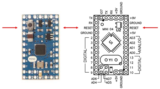
04-04-2013 02:23 PM
- Mark as New
- Bookmark
- Subscribe
- Mute
- Subscribe to RSS Feed
- Permalink
- Report to a Moderator
This is good. We are on the same page! The button should be the reset switch as shown on the schematic.
Have you added the switch and resistor shown in the diagram of your USB-UART? They are not necessary since there is a reset switch and resistor already attached to pin 29 of the chip.
With the Micro attached to your USB-UART normally, there should be 3 to 5 volts between the reset pin at one of your arrows and ground, with or without the cap and DTR connection. Hitting the reset button should pull this down to 0.
JohnCS
04-05-2013 02:44 AM
- Mark as New
- Bookmark
- Subscribe
- Mute
- Subscribe to RSS Feed
- Permalink
- Report to a Moderator
I haven't included an additional reset button.
The voltage between the reset pin and ground (as well as between DTR and reset without cap) measures 4.7 V before and after pressing the button. It changes to 0 V upon pressing reset.
04-05-2013 01:09 PM
- Mark as New
- Bookmark
- Subscribe
- Mute
- Subscribe to RSS Feed
- Permalink
- Report to a Moderator
Curiouser and curiouser!
Can you load and run an Arduino sketch that has two way communications like Example/communications/ ASCIItable or ReadASCIIstring?
JohnCS
04-06-2013 09:45 AM
- Mark as New
- Bookmark
- Subscribe
- Mute
- Subscribe to RSS Feed
- Permalink
- Report to a Moderator
The LIFA sketch I am using is reading voltage from a thumbstick poti for controlling a stepper motor. So the communication seems to work properly.
04-08-2013 02:41 PM
- Mark as New
- Bookmark
- Subscribe
- Mute
- Subscribe to RSS Feed
- Permalink
- Report to a Moderator
As near as I can tell from your explanation, you have wired it up correctly and all the right things seem to be happening, except the auto-reset. At this point, I would try this with another Arduino and/or USB-USART connector.
Have you tried uninstalling LIFA and reinstalling it? That has worked for some people who had this problem.
JohnCS
04-10-2013 03:42 AM
- Mark as New
- Bookmark
- Subscribe
- Mute
- Subscribe to RSS Feed
- Permalink
- Report to a Moderator
I have tried my VI with the arduino UNO and Mega and auto reset works properly with the boards. Do you still recommend reinstalling LIFA even though auto reset works with the other boards? This is really confusing!
I will buy a new USB/UART converter and test it again with the mini...
- « Previous
- Next »
