- Subscribe to RSS Feed
- Mark Topic as New
- Mark Topic as Read
- Float this Topic for Current User
- Bookmark
- Subscribe
- Mute
- Printer Friendly Page
- « Previous
-
- 1
- 2
- Next »
LIFA Base starts motors running on upload
11-10-2013 10:36 PM
- Mark as New
- Bookmark
- Subscribe
- Mute
- Subscribe to RSS Feed
- Permalink
- Report to a Moderator
Thanks for the quick replay Nathan. Unfortunately, the code I wrote previously looked just like that example and I have not been able to get it to work.
Labview is definitely communicating with the arduino. When running this example, I can measure voltage from pin 5 and 6 on my multimeter and they track well with the PWM signal commanded from each motor slider respectively.
My only guess is that maybe the appropriate pins to use are different for my shield than they are for the adafruit one (though OSEPP says their shield works with adafruit commands)
I have successfully gotten the motor and shield to work by just using the adafruit motor library and loading some basic codes directly onto the arduino (not using the labview interface). This gives me confidence that the hardware is all working together correctly. But this is higher level code (not just pwm and binary signals to different pins like it is with the labview interface).
Using a variant on your attached VI, I cycled through all the various possibilities of channel combinations, and still nothing seemed to work. I know I am missing something but I can't figure it out.
Summary:
I know the hardware, motor, battery, etc.. work correctly together
I know labview is communicating with the board and shield
I just must not be sending all of the correct commands from labview to the arduino
Any help would be greatly appreciated,
-Tom
02-25-2014 10:48 PM
- Mark as New
- Bookmark
- Subscribe
- Mute
- Subscribe to RSS Feed
- Permalink
- Report to a Moderator
seeing your work is similar like mine.
I have to program an encoder dc gear motor using arduino uno.I am searching for simple coding online
and tutorials but unfortunately i am unable to do.
is any1 have sample
send me please
02-26-2014 01:46 PM
- Mark as New
- Bookmark
- Subscribe
- Mute
- Subscribe to RSS Feed
- Permalink
- Report to a Moderator
I have worked with a shield to operate a DC motor in the past with labview. The shield has 4 motor connections. If you notice the motor that is included with the shield it has 4 pins. These pins when powered in sequence turn the motor (Position 1, 2, 3, and 4). For the motor to turn, power can only be applied to only 1 pin at a time. To turn the motor one complete rotation, the coding logic should be as follows where 0 represents off and 1 represents on: 1000 0100 0010 0001.
To have this work with the uC, you simply have to plug the shield pins to the digital I/O pins on the uC and apply proper supply voltage to the shield to power the motor. With the LIFA interface loaded onto the uC, you can assign and set 4 pins on the uC that connects to shield and create a loop that sequentially sets 1 pin high and the rest low.
If you still cannot figure it out, let me know.
08-25-2015 01:06 AM
- Mark as New
- Bookmark
- Subscribe
- Mute
- Subscribe to RSS Feed
- Permalink
- Report to a Moderator
Hi,
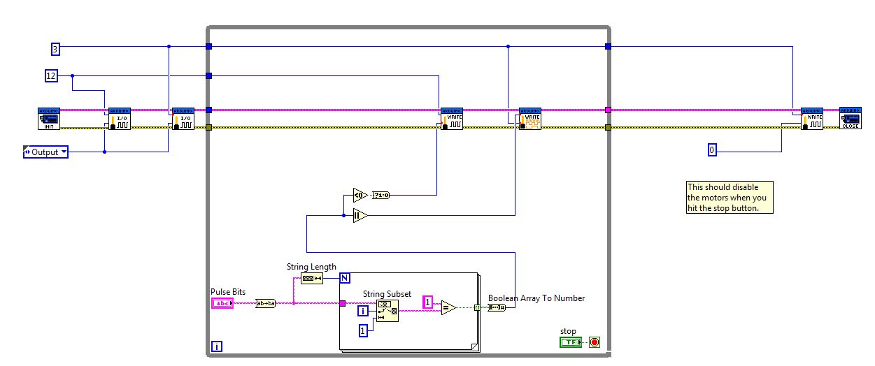
If i'm using a arduino motor shield together with the arduino uno, how do i set my pin. In order to create a loop that sequentially sets 1 pin high and the rest low. As i'm currently doing a train project of using labview interface with arduino. i wanted to create a output pattern when my PWN cycle is at "50", but i only saw a duty cycle pattern being generated.
Are you able to help me solve this issue?
The below is my labview design: i using the example here to do my testing of the train movement of forward & reverse.
- « Previous
-
- 1
- 2
- Next »
