From 11:00 PM CDT Friday, May 10 – 02:30 PM CDT Saturday, May 11 (04:00 AM UTC – 07:30 PM UTC), ni.com will undergo system upgrades that may result in temporary service interruption.
We appreciate your patience as we improve our online experience.
From 11:00 PM CDT Friday, May 10 – 02:30 PM CDT Saturday, May 11 (04:00 AM UTC – 07:30 PM UTC), ni.com will undergo system upgrades that may result in temporary service interruption.
We appreciate your patience as we improve our online experience.
02-02-2016 08:15 AM
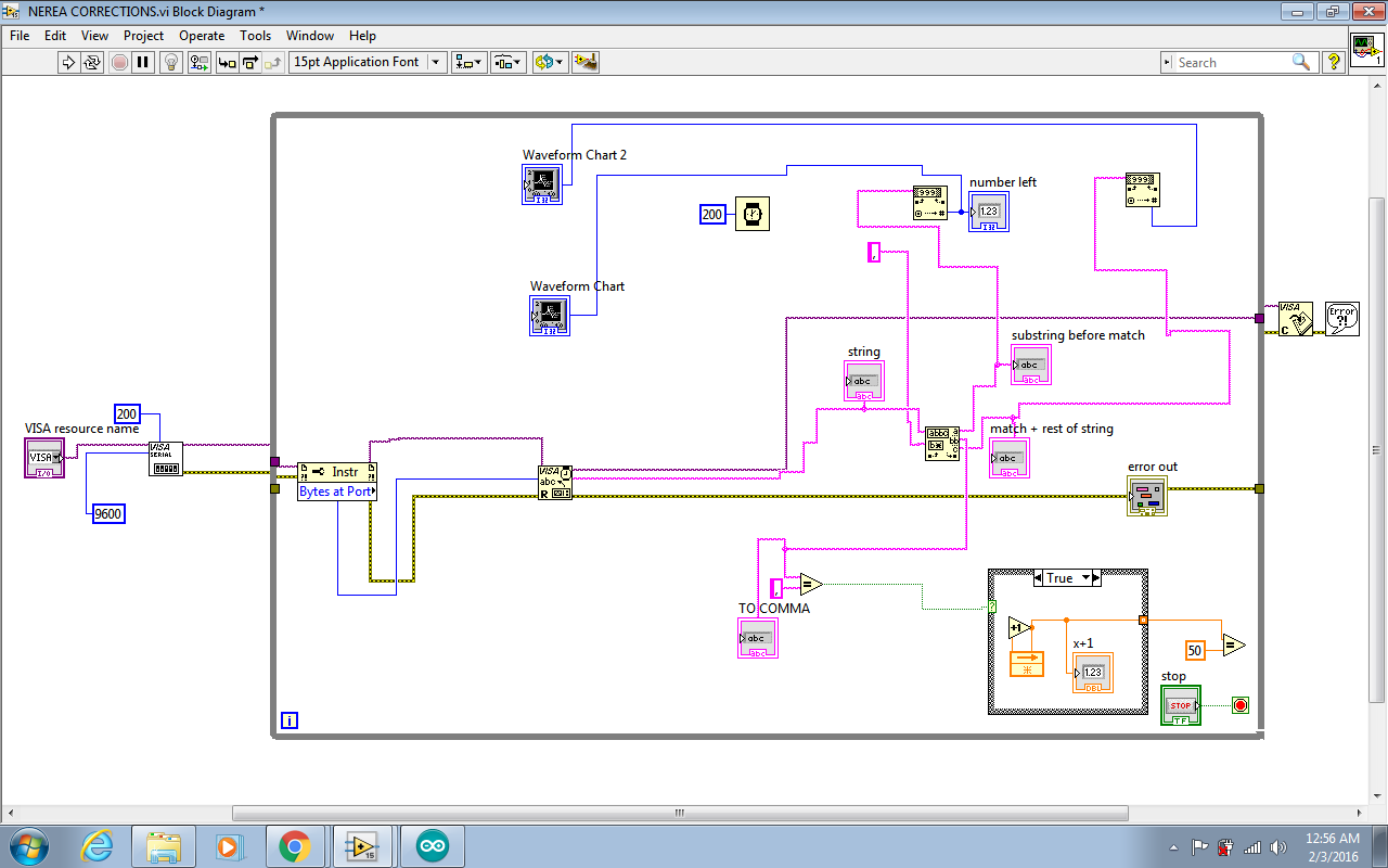
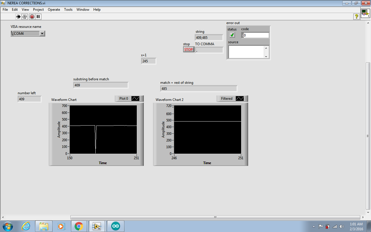
Hello to everyone.I have two pt1000 sensors and ive connected them to an arduino from where then im sending the adc value to labview.In to the labview programm i have a visa config ,a byte to port ,a visa read and becouse im taking the values as an example 452,248 i have a match pattern and from there i do the conversion from string to decimal nr and then a graphic representation .Im not sure yet but something is wrong whith my timings or with my buffer. Im trying to do the meassurements in real time. If i put the wait delay of the loop in to labview the grafical representation is allwright but after a while it gives me spikes and eventually gets crazy.could someone help me plz what am i doing wrong. I tryied to put a stop read visa charracter in to the arduino code (/n).but that didnt do the job.Help anyone ....?
02-02-2016 05:16 PM
Are you using LIFA or LINX? What are you using for a signal conditioner to convert a change in resistance to a voltage suitable for use with an Arduio Uno 0 to 5 volt DC range?
hrh212
02-02-2016 07:07 PM
Hi there and thanks for the response.Im using an arduino mega.To obtain the value from pt 1000 i just use a voltage divider using a presicision resistor of 1000 kohm in series .I take the analogue value of the divider and feed it to arduino and from there im printing it to the serial port .in this way (valuept1,valuept2) (/n) . Its a simple code .Im planning to do the conversion from adc value to propper temperature value later afer i manage to stabilize the values.
// These constants won't change. They're used to give names
// to the pins used:
const int analogInPinLEFT = A0; // Analog input pin that the potentiometer is attached to
const int analogOutPinRIGHT =A1; // Analog output pin that the LED is attached to
// constants of the Pt 1000 formulas
int LEFT = 0; // value read from the left motor
int RIGHT = 0; // value read from the right motor
void setup() {
// initialize serial communications at 9600 bps:
Serial.begin(9600);
INTERNAL2V56 ;
}
void loop() {
// read the analog in value:
LEFT = analogRead(analogInPinLEFT);
RIGHT = analogRead(analogOutPinRIGHT);
// print the results to the serial monitor:
Serial.print(LEFT);
Serial.print(",");
Serial.print(RIGHT);
Serial.print("\n");
// wait milliseconds before the next loop
// for the analog-to-digital converter to settle
// after the last reading:
delay(200);
}
to answer your question im not using Lifa or Linx in that matter .Do i have to purchase them if i dont have them ?
So my real problem is that spike that you see and comes on both values at the 186th meassured value as im counting the commas just to make sure where exactly is it happening.Propably a buffer overflow but i cant be sure as im amatuer in labview and arduino.
02-02-2016 11:49 PM
I suggest you use LINX. Both LFA and LINX are free programs provided by National Instruments for promoting the use of Labvierw by students. National instruments no longer supports LIFA. For your application LINX has an example Analog Read N Channels.VI. With LINX you do not write sketches. Instead when you install LINX the installer installs LINX examples in Labview and an application program Interface, API, in your Arduino board. The Analog Read N channels.VI then sends commands to the API to get the analog data. The API then returns the requested data.
The following web page will get you started with LINX
https://www.labviewmakerhub.com/doku.php?id=libraries:linx:start
hrh212
02-03-2016 03:12 AM
Hello hrh212 and thanks again for your response.I did follow your instructions and downloaded and installed Linx .I uploaded the Linx firmware on to my arduino.I opened the example you sugested but doesnt work.It gives me the error 5003.I checked all the cables and all the connections everything seems to be fine.I even uploaded the firmware couple of times just to make sure.I am choosing the correct port so i dont know what to do from now on ......
02-03-2016 03:50 AM
Hi again , i tryied the basic example of Linx .The one controlling a led light with a blink button and i had the same issue.Error 5003.Propably is something to do with the interface with the arduino but dont know what to check .
02-03-2016 06:43 AM
Please help me as fast
My USB sees it self at Arduino COM 3
I can compile and when it sends I either get a Busy messege, or this
Arduino: 1.6.6 (Windows 7), Board: "Arduino آNano"
Sketch uses 1,030 bytes (3%) of program storage space. Maximum is 32,256
bytes.
Global variables use 9 bytes (0%) of dynamic memory, leaving 2,039 bytes
for local variables. Maximum is 2,048 bytes.
avrdude: stk500_recv(): programmer is not responding
avrdude: stk500_getsync() attempt 1 of 10: not in sync: resp=0x75
avrdude: stk500_recv(): programmer is not responding
avrdude: stk500_getsync() attempt 2 of 10: not in sync: resp=0x75
avrdude: stk500_recv(): programmer is not responding
avrdude: stk500_getsync() attempt 3 of 10: not in sync: resp=0x75
avrdude: stk500_recv(): programmer is not responding
avrdude: stk500_getsync() attempt 4 of 10: not in sync: resp=0x75
avrdude: stk500_recv(): programmer is not responding
avrdude: stk500_getsync() attempt 5 of 10: not in sync: resp=0x75
avrdude: stk500_recv(): programmer is not responding
avrdude: stk500_getsync() attempt 6 of 10: not in sync: resp=0x75
avrdude: stk500_recv(): programmer is not responding
avrdude: stk500_getsync() attempt 7 of 10: not in sync: resp=0x75
Problem uploading to board. See
http://www.arduino.cc/en/Guide/Troubleshooting#upload25
<http://www.arduino.cc/en/Guide/Troubleshooting#upload> for suggestions.
avrdude: stk500_recv(): programmer is not responding
avrdude: stk500_getsync() attempt 8 of 10: not in sync: resp=0x75
avrdude: stk500_recv(): programmer is not responding
avrdude: stk500_getsync() attempt 9 of 10: not in sync: resp=0x75
avrdude: stk500_recv(): programmer is not responding
avrdude: stk500_getsync() attempt 10 of 10: not in sync: resp=0x75
02-03-2016 01:44 PM
This web page indicates others have had problems using LINX with an Ardiuino Mega.
<https://www.labviewmakerhub.com/forums/viewtopic.php?f=12&t=33>
Scroll down the page to the last post in the thread.and try the solution suggested by Sam Kristoff.
If that doesn't fix the problem search the LIKNX forums Using "Error 5003". You will get a lot of hits and will need to spend some time figuring out which answer is appropriate for your situation.
hrh212
02-03-2016 01:49 PM
To hacker17
Please don't hijack an existing thread. A different subject requires a new thread.
hrh212
04-18-2016 10:28 AM
Did you load the firmware to the Arduino?
That has to be done first.
Tools -> MakerHub -> Linx -> Firmware
Make sure the COM port is correct (for me it wants to automatically use AST*****, but my board is on COM4)
After the upload you should be able to run the example, then create your own
LINX has many VI's pre-made that can be used
Ciao
