- Subscribe to RSS Feed
- Mark Topic as New
- Mark Topic as Read
- Float this Topic for Current User
- Bookmark
- Subscribe
- Mute
- Printer Friendly Page
Reading SPI from MCP3201
08-19-2012 08:02 AM
- Mark as New
- Bookmark
- Subscribe
- Mute
- Subscribe to RSS Feed
- Permalink
- Report to a Moderator
Hey Guys,
My name is Fernando and I am from Brazil.
I am working on a litle project to read a PT100 temperature sensor using the MCP3201 after some aplification and filters. I have attached the datasheet for the MCP.
I am having problems to build a vi just to read what the MCP3201 is giving me through the SPI. My knowledge of programming, bits and bytes is kind of null.
I have read other posts but each has some little diferences and I couldn't receive any data.
From what I understood the MCP3201 needs to have is CS at low to provide the info. But it seems that the SPI Send and Receive is not changing the pin to high or low as required by the MCP.
PT100 Temperature Sensor
MCP3201 - ADC 12 bits
Arduino Duemilanove
I am using the pins as follows:
Pin 10 - CS
Pin 12 - Miso
Pin 13 - Clock
SPI Bit order - MSB First
SPI Mode - 0
SPI Clock Divider - (I got some questions on this) The datasheet says 1.6 Mhz and the arduino is 16 Mhz. The options are 2, 4, 8, 16, 32, 64, 128. Should I include 10 on the code?
I really don't understand what is the input on SPI data (SPI Send Receive) that is required to change the CS(pin 10) from high to low. I can add a constant, but I couldn't figure it out.
Do I have to make changes on the Interface Code? Or will it work on Labview just setting up the correct vi?
Can anyone help me?
I will attach the vi that I am working on asap.
Thanks in advance.
Fernando
08-19-2012 05:41 PM
- Mark as New
- Bookmark
- Subscribe
- Mute
- Subscribe to RSS Feed
- Permalink
- Report to a Moderator
Guys,
I am attaching the VI I am working with. I am positive that it is not correctly done, but I would like your comments.
As the MCP 3201 is a 12 bit DAC, we would only receive two "words"of 8bit, making it 16bit having the leaving the 4 last bits unused.
I am supposed to read a small voltage, so I will have to convert the array I get to decimal.
I saw in another post (by Sam) that I will need to receive the 16 bits in two pieces and join them to make a hole sequence.
Sam, give me some help.
Thanks
Fernando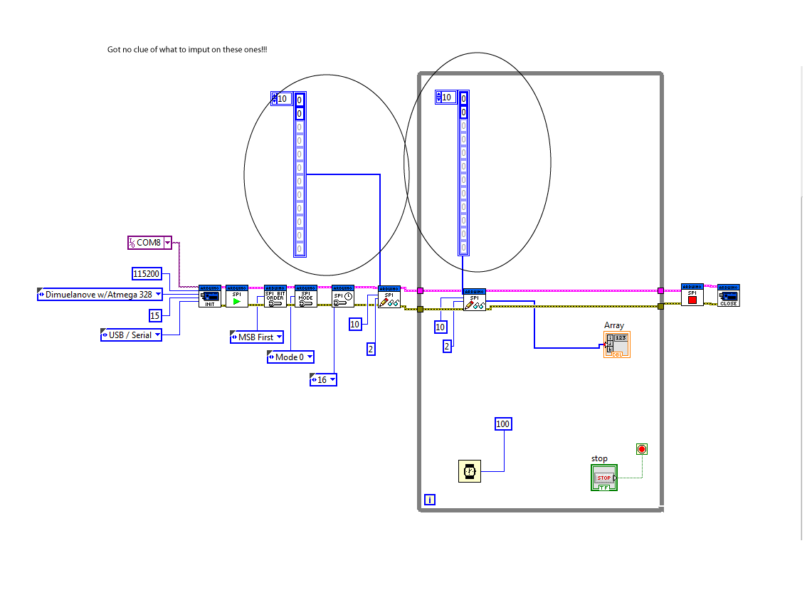
08-20-2012 12:33 AM
- Mark as New
- Bookmark
- Subscribe
- Mute
- Subscribe to RSS Feed
- Permalink
- Report to a Moderator
I've written VIs for some SPI based sensors (I'd have to go back and review how many of them I've had confirmed working). Regardless, I'm convinced that SPI is not implemented in such a way that it works for all SPI devices. I could be totally wrong because as I've been digging into the Arduino library for SPI and I'm unable to fully understand how it works. I did have one sensor that said "SPI Compatible" but I could never get it working and found a sketch online that did it a different way and it worked perfect.
My suggestion to you is to find an Arduino sketch online somewhere that actually works. Then, post a link here so that I can look at it and see a way that I might be able to help you.
08-20-2012 12:49 AM
- Mark as New
- Bookmark
- Subscribe
- Mute
- Subscribe to RSS Feed
- Permalink
- Report to a Moderator
Nathan,
Thanks for the reply.
The only code I found is this one, and I have been looking for some for a while now. Maybe it will help.
http://www.rocketnumbernine.com/2009/04/26/using-spi-on-an-avr-1
Can you tell me what am I supposed to input on SPI data? I have tried 0,0 (two bytes). But I don't know if this is the correct info that I am supposed to send. Maybe I don't have to send anything, just get the CS Pin to low to receive the hole block of 12 bits.
From the datasheet, what I understood is that I need to get the CS to low to get a reading of 12 bits. And from a past post from Sammy_K I understood that the SPI Send Receive does that.
Thanks for your support.
08-20-2012 11:55 AM
- Mark as New
- Bookmark
- Subscribe
- Mute
- Subscribe to RSS Feed
- Permalink
- Report to a Moderator
Guys,
I got a new VI. But I think that the SPI Send and Receive is not working properly. The values, they change with no logic.
Please find attached my vi.
I need to shift 7 bit on byte one to the left and 1 bit on byte 2 to the right and them join them together.
AT 21.6 Celsius I am supposed to read around 834 mV.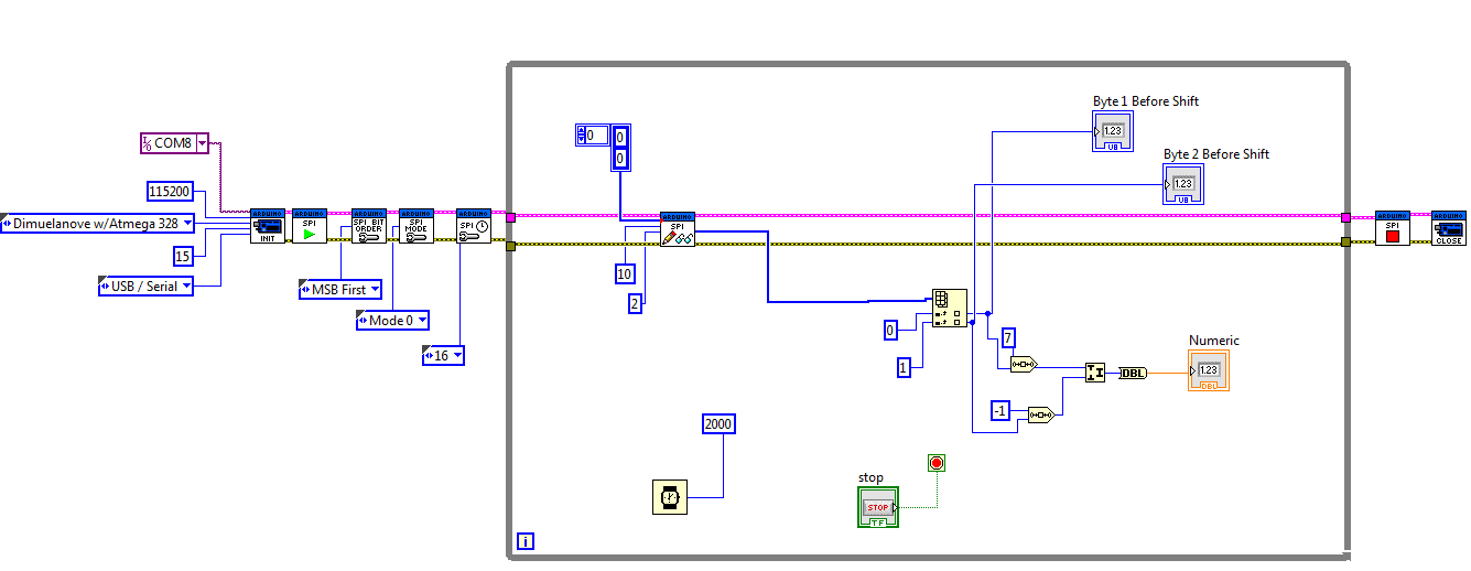
Can anyone check if my vi makes sense.
Thanks
Fernando
08-20-2012 04:48 PM
- Mark as New
- Bookmark
- Subscribe
- Mute
- Subscribe to RSS Feed
- Permalink
- Report to a Moderator
NathanB. wrote:
I've written VIs for some SPI based sensors (I'd have to go back and review how many of them I've had confirmed working). Regardless, I'm convinced that SPI is not implemented in such a way that it works for all SPI devices. I could be totally wrong because as I've been digging into the Arduino library for SPI and I'm unable to fully understand how it works. I did have one sensor that said "SPI Compatible" but I could never get it working and found a sketch online that did it a different way and it worked perfect.
My suggestion to you is to find an Arduino sketch online somewhere that actually works. Then, post a link here so that I can look at it and see a way that I might be able to help you.
Nathan,
I got another code that is working now. With a little help from a friend in USA. It sends the correct ADC data to the serial monitor.
I attached it here. It does everything that the MCP Datasheet asks.
But I can't get the SPI Send And Receive to send out a constant array data. It keeps changing. If the voltage that the ADC is sending to it is stable it shouldn't be reading different values all the time. I guess something needs to be changed, either on my VI or on the SPI Send And Receive Vi.
Can you take a look at the code a see if you can help me?
Thanks
Fernando
08-20-2012 06:26 PM
- Mark as New
- Bookmark
- Subscribe
- Mute
- Subscribe to RSS Feed
- Permalink
- Report to a Moderator
Another user recently posted and I'm quite sure they found a mistake in the LIFA firmware (affecting SPI) in version 2.1.1.69 but this will need to be confirmed. If that is true, then it might fix some issues.
08-20-2012 06:33 PM
- Mark as New
- Bookmark
- Subscribe
- Mute
- Subscribe to RSS Feed
- Permalink
- Report to a Moderator
Nathan,
Is it that, the message posted by Chupakabra?
Do you think we could have that checked soon? Or maybe it will take some time?
I am kind of in a limbo here and I need to get this working as soon as possible.
Did you check my Vi? Is that correct?
Thanks anyway for your prompt replies.
Regards
Fernando
08-20-2012 06:35 PM
- Mark as New
- Bookmark
- Subscribe
- Mute
- Subscribe to RSS Feed
- Permalink
- Report to a Moderator
Well, regarding the firmware, you can easily change it in your firmware and test it. I'll look at your VI right now.
EDIT:
You should shift bits then add OR use Join Numbers NOT both. Also, in the sketch, they send 0xFF and not 0 like you are trying to do. Not sure if that is a major thing or not but it is certainly one thing that is different.
08-21-2012 03:21 AM
- Mark as New
- Bookmark
- Subscribe
- Mute
- Subscribe to RSS Feed
- Permalink
- Report to a Moderator
Nathan,
Regarding the firmware I won't change it by myself, because I wouldn't know what to do.
Regarding the 0xFF and 0, I used both on arduino and got the same results.
How do I go about doing the logicla shift?
I got to:
Following the Arduino Code:
put the bytes into an int.
shift upper byte 7 bits left,
shift lower byte 1 bit right & make bit 7 a 0,
add the two together,
and make the upper 4 bits 0
Can you help me out?
Thanks again
Fernando
NathanB. wrote:
Well, regarding the firmware, you can easily change it in your firmware and test it. I'll look at your VI right now.
EDIT:
You should shift bits then add OR use Join Numbers NOT both. Also, in the sketch, they send 0xFF and not 0 like you are trying to do. Not sure if that is a major thing or not but it is certainly one thing that is different.
