- Subscribe to RSS Feed
- Mark Topic as New
- Mark Topic as Read
- Float this Topic for Current User
- Bookmark
- Subscribe
- Mute
- Printer Friendly Page
multiple digital output pin problem, init.vi setting digital pin
02-22-2013 01:11 PM
- Mark as New
- Bookmark
- Subscribe
- Mute
- Subscribe to RSS Feed
- Permalink
- Report to a Moderator
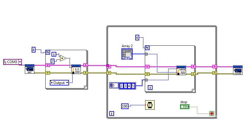
I wrote a 4 bit logic control VI and I am testing it with LEDs. I've attached a pic of the block diagram and the VI itself. Something funny is happening and I can't figure it out. When I run it, the 3 LSB bits of the array turn on regardless of what my front panel controls are set at, then the proper ones turn on/off after maybe half a second. After that it works fine and I can control each bit properly. Those pins are going high during the init.vi. Shouldn't the init.vi just initiate communication and not actually set digital pins high? Please help.
02-22-2013 02:33 PM
- Mark as New
- Bookmark
- Subscribe
- Mute
- Subscribe to RSS Feed
- Permalink
- Report to a Moderator
I'm guessing this has to do with when you set the pin mode, it sets a random default value. Then, it starts your 100ms loop and sends the values from the front panel. One thing that you could do to test this theory is to turn on execution highlighting so that you know where in the code you are when this unwanted behavior occurs. So, do this and see what you find.
P.S. When posting VIs, please save it for LabVIEW 2009 so that those of us without the latest version can still help (since LIFA, as far as I know, is not dependent on LabVIEW version).
02-22-2013 02:59 PM
- Mark as New
- Bookmark
- Subscribe
- Mute
- Subscribe to RSS Feed
- Permalink
- Report to a Moderator
Thanks for your quick response.
I turned on execution highlighting and ran it and discovered those pins are definately turning on during the init.vi. After I stop the VI(stop button for while loop), the bits remain in their last state, when I rerun it, during the init.vi all bits turn off for a split second, then the 3 LSB bits turn on for a split second(regardless of front panel controls), then they turn on/off to reflect the front panel.
Another piece of info: If I unplug the usb cable then replug, those same 3 bits come on, regardless of what they were before I unplugged the cable. Seems to be some sort of default. If it is, how can I set the default for all digital pins to be off?
Any ideas?
02-22-2013 03:02 PM
- Mark as New
- Bookmark
- Subscribe
- Mute
- Subscribe to RSS Feed
- Permalink
- Report to a Moderator
I edited my first post and attached a 2009 version of the VI.
02-23-2013 08:39 PM
- Mark as New
- Bookmark
- Subscribe
- Mute
- Subscribe to RSS Feed
- Permalink
- Report to a Moderator
I think I remember some one else asking this question before. The best solution that I remember is to edit the firmware to set those pins false when it boots. However, I'm not entirely sure that solve the problem completely. If you can find that thread I believe it will be at least somewhat helpful to you.
Also, depending on what you are doing with your other pins, you may be able to use the "Digital Write Port.vi" to send all the info simultaneously (requires all 14 pins to be set to output).
02-25-2013 03:13 AM
- Mark as New
- Bookmark
- Subscribe
- Mute
- Subscribe to RSS Feed
- Permalink
- Report to a Moderator
Hello,
I think the thread mentioned by Nathan was this one :
https://decibel.ni.com/content/message/41624#41624
If so, the proposed solution was not on the firmware side, but in the .vi, to force the state before closing, so that the state is known for further opening.
However, I tried this solution proposed by pedro without success on a UNO, so I'am still struggling with the same issue...
If manage to deal with it let us know !
Antoine
02-25-2013 10:38 AM
- Mark as New
- Bookmark
- Subscribe
- Mute
- Subscribe to RSS Feed
- Permalink
- Report to a Moderator
I have added a command to force the lines low before the close which does turn them off and they do remain off after the my program closes, but when I rerun the program, the same things occurs, those 3 lines go high before I am able to control them. It definately occurs during the init.vi. I haven't found any posts on the firmware side that might solve this problem. I am still investigating and will post what I find. Please help if you can! Thanks.
02-25-2013 11:02 AM
- Mark as New
- Bookmark
- Subscribe
- Mute
- Subscribe to RSS Feed
- Permalink
- Report to a Moderator
I thought I remember even one more thread about this but I'm not able to find it.
If you run an Arduino program like the blink example in the Arduino IDE, what do the pins in question show then?
My first instinct would tell me to add code to the firmware (the part that runs when Arduino gets power) to set these pins to a desired ouput. Then, they will be this same output when you use "Init.vi". However, I'm not sure that if when you set the pin mode after initializing it changes the actual output value or not. That is something that could easil be tested.
02-25-2013 06:17 PM
- Mark as New
- Bookmark
- Subscribe
- Mute
- Subscribe to RSS Feed
- Permalink
- Report to a Moderator
So I ran the blink example in the Arduino IDE and it works perfect. The pins in question never turn on.
If I reload original firmware, those 3 pins come on and stay on.
If I load firmware with modification(set 4 pins low before main loop), 2 pins flash for a split second, then stay off. I unplug usb then replug, same thing, quick LED flash.
I ran my LabVIEW program with highlight execution and the same 2 LEDs do the same quick flash at the VISA Configure Serial Port VI inside the Init.VI
Seems to be the result of establishing the serial connection, whether LabVIEW does it through VISA or the firmware does it on initial plugging in of the USB cable.
I'm now using pins 6-9 as opposed to 2-5. These new pins are quiet and act as expected. If anyone figures what is giong on with the other pins, please post. Thanks to everyone who offered help on this.
02-26-2013 02:11 PM
- Mark as New
- Bookmark
- Subscribe
- Mute
- Subscribe to RSS Feed
- Permalink
- Report to a Moderator
Thank you for posting this!
I have been trying to overcome this exact issue for the past 2 days!
In my case I was tring to trigger a dual coil latching relay. Every time the Arduino would boot up, it would set the pins to HIGH for a split second and then behave normally until it received a serial connection and then the same thing would occur. As far as I can work out, the reset on serial connection is normal. The brief HIGH output however is not, and was causing me major issues as the relay would trigger randomly.
I tried various things to fix it, pull-down resistors, playing with the pin states in setup() and trying to modify the init vi. None of which helped in the slightest. As a last resort I figured I would switch pins to see if that helped, and I found that pins >5 seemed to behave normally(I will try to confirm this today).
As you asked, I would love to know if anyone has a fix for this. Thankfully for the moment I don't need all of the pins, otherwise I would have to choose a different device altogether!
I know that the Arduino itself sets all of the pins to INPUT(except Pin 13) which will be floating somewhere between 0-5V if they aren't pulled up/down. This makes me think it may have something to do with the LIFA_Base firmware?
So to summarise, I have been having the exact same issues as yourself and haven't found a solution so far.
