- Subscribe to RSS Feed
- Mark Topic as New
- Mark Topic as Read
- Float this Topic for Current User
- Bookmark
- Subscribe
- Mute
- Printer Friendly Page
spi with an ltc 2400
11-30-2011 10:09 AM
- Mark as New
- Bookmark
- Subscribe
- Mute
- Subscribe to RSS Feed
- Permalink
- Report to a Moderator
Hello all:
objective:
-> trying to inclrease the resolution of the arduino to mor ethan 10 bits
i found an article on the arduino playground that uses a high resolution adc to increase the resolution of the arduino
i ran the code and compiled it using c and it successfully read the analog signal with better resolution than 10 bits.
i would like to do the same using the LIFA, but i have not been succesfull in it.
any help will be apreciated.
thanks
12-02-2011 03:00 PM
- Mark as New
- Bookmark
- Subscribe
- Mute
- Subscribe to RSS Feed
- Permalink
- Report to a Moderator
Caluctra,
What have you tried so far? What have your results been when using LIFA? Are you getting errors, incorrect data, no data, ...? Can you post your code? Are you trying to modify the firmware or just using the LIFA SPI VIs?
-Sam K
LIFA Developer
12-04-2011 04:06 PM
- Mark as New
- Bookmark
- Subscribe
- Mute
- Subscribe to RSS Feed
- Permalink
- Report to a Moderator
Sammy K,
first of all thanks for replaying to my post.
what i have done is trying reading the datasheet of the adc, and undersetand how the spi works there, and implemented on the application with lifa.
iam trying to use the life spi vis, pretty much i want to first be able to read something
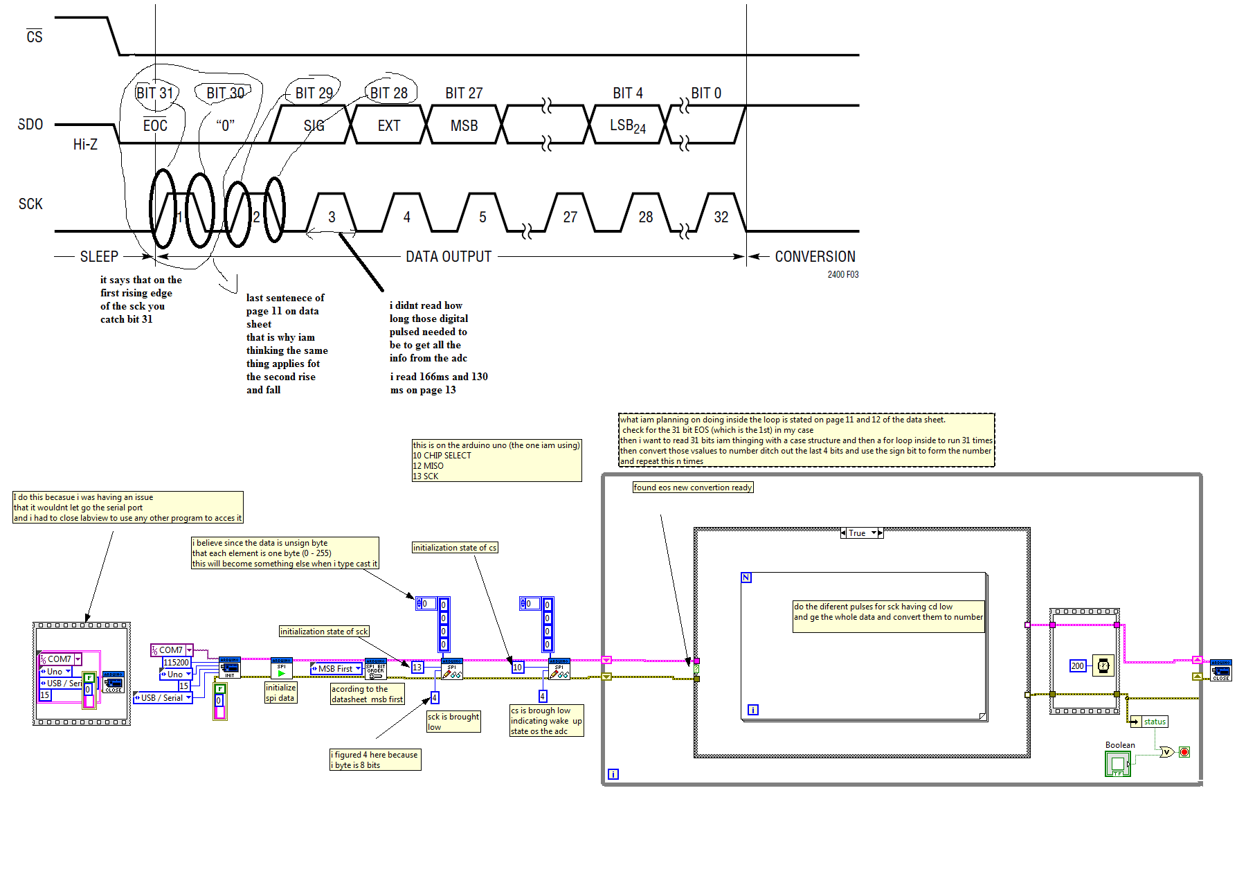
this are things that i believe are important on the comunication.
-> the adc after each convertions enters a sleep mode and remains there until CS is brought to low.
-> CS low wakes the adc as well as enables the and enables the digital oputput generation
-> a low to high transition of CS during the data output transfer abourts the data transfer and starts a new convertion.
-> during CS on high (adc asleep) the SDO pin is detached and can be used as convertion status output which can be observed by waking up the adc. (i dont underestand this fully)
-> the ltc2400 initially performs a convertions and then goes to sleep mode (low power)
-> Fo is connected to Vcc therefore iam inteding to use the internal ocilator of the adc. digital filter first null is at 50 Hz (dont underestand the first null term here)
-> SDK bidirectional digital clock pin, and it says that when using internal oscillator SCK is used as digital output as well
-> "bit 27 through bit 4 are the 24 bit convertion result MSB first
-> bit 29 is the sign indicator
-> the output stream is 32 bits long
-> last 4 bits can be discarted without loosing resolution
i also post a .jpeg with the code i have as well as figure 3 on the data sheet with my thoughts and questions.
iam sure many of them are trivial but this is my first time trying sdomething like this.
i will also post the datasheet of the adc.
it will not let me upload any thing else other than images. no vis nor pdfs
cant explain whats going on.
finally is the support with ni includes arduino lifa?
regards
12-05-2011 09:48 AM
- Mark as New
- Bookmark
- Subscribe
- Mute
- Subscribe to RSS Feed
- Permalink
- Report to a Moderator
Caluctra,
It looks like you are miss-using the SPI Send Receive VI. You configuration look good except where you call the two SPI Send Receive VIs. These VIs are actually used to shift out data and read incoming data from the device. You are correct in setting the word size to 4 bytes (32 bits), however you only need to tell it which pin to use as chip select when you actually want to send data. The chip select pin is toggled automatically for you based on the word size you select.
For example:
Say you want to send four 1 byte words to a sensor with chip select wired to DIO 4. Call the SPI Send Receive VI with a Data array containing the 4 bytes cs set to 4 and word size set to 1. This will do the following:
Set CS (Pin 4) Low
Shift out 1 byte
Buffer 1 byte input
Set CS High (because the word size is set to 1 byte)
Set CS (Pin 4) Low
Shift out 1 byte
Buffer 1 byte input
Set CS High (because the word size is set to 1 byte)
Set CS (Pin 4) Low
Shift out 1 byte
Buffer 1 byte input
Set CS High (because the word size is set to 1 byte)
Set CS (Pin 4) Low
Shift out 1 byte
Buffer 1 byte input
Set CS High (because the word size is set to 1 byte)
Return array of 4 bytes read.
So in your case when you actually want to write or read data you would call the SPI Send Receive VI with CS set to your CS pin, word size set to 4 and an array of 4 bytes. This will set CS low, send 4 bytes to the device, read 4 bytes from the device and then return the 4 bytes read. Also check to make sure you don't use a CS pin that is being used as a Clock of data line for example you cannot use pin 13 as CS on the Uno because it is SCK http://arduino.cc/en/Main/ArduinoBoardUno
Let us know if this helps you out or if you have more questions.
-Sam K
LIFA Developer
12-08-2011 09:49 AM
- Mark as New
- Bookmark
- Subscribe
- Mute
- Subscribe to RSS Feed
- Permalink
- Report to a Moderator
Hello Sam,
thanks again for replaying.
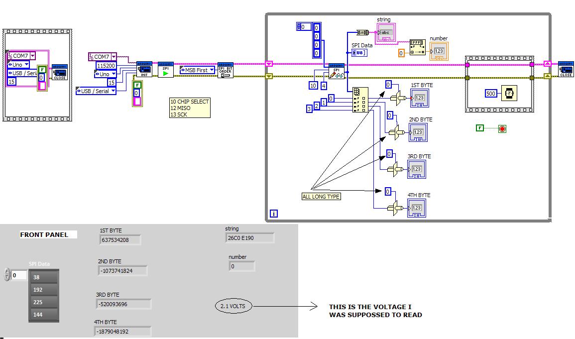
I have had partially success after reading your post.
I am reading what I believe is the voltage of interest, but in order to be sure I need to convert the 4 bytes (type unsign byte U8) to something mininfull to me, such as (DBL). until now i have not been successfull in doing so, and Iam uploading a .jpeg file to show you.
12-08-2011 10:02 AM
- Mark as New
- Bookmark
- Subscribe
- Mute
- Subscribe to RSS Feed
- Permalink
- Report to a Moderator
caluctra,
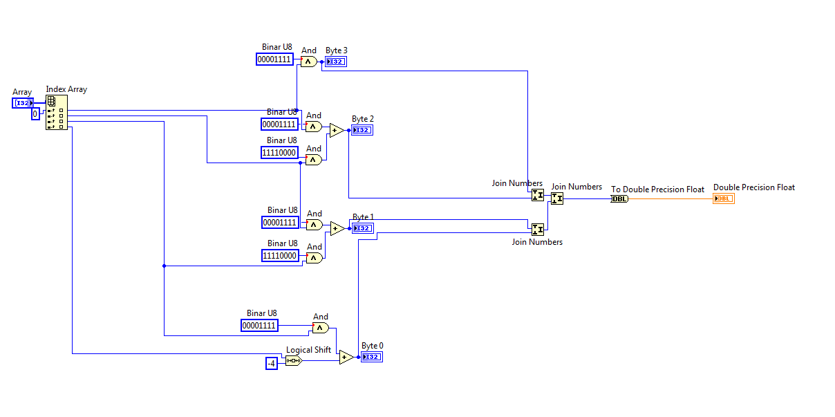
Instead of type casting the bytes as longs you will need to join then first, then type cast them to double.
First decide if the bytes are sent back most significant byte (MSB) first or least siginificant byte first (LSB). Once you know the order you can use the Join Numbers primitive to take two 8-bit numbers and join them into a single 16 bit number (order matters!!!). You can cascade the join jumbers VI to join all 4 bytes into a single 32 bit number, then change its representation to double.
Assuming MSB First:
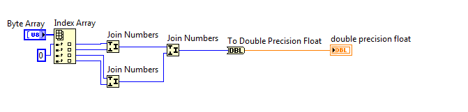
Let us know if you have more questions. You are getting close!
-Sam K
LIFA Developer
12-08-2011 11:53 AM
- Mark as New
- Bookmark
- Subscribe
- Mute
- Subscribe to RSS Feed
- Permalink
- Report to a Moderator
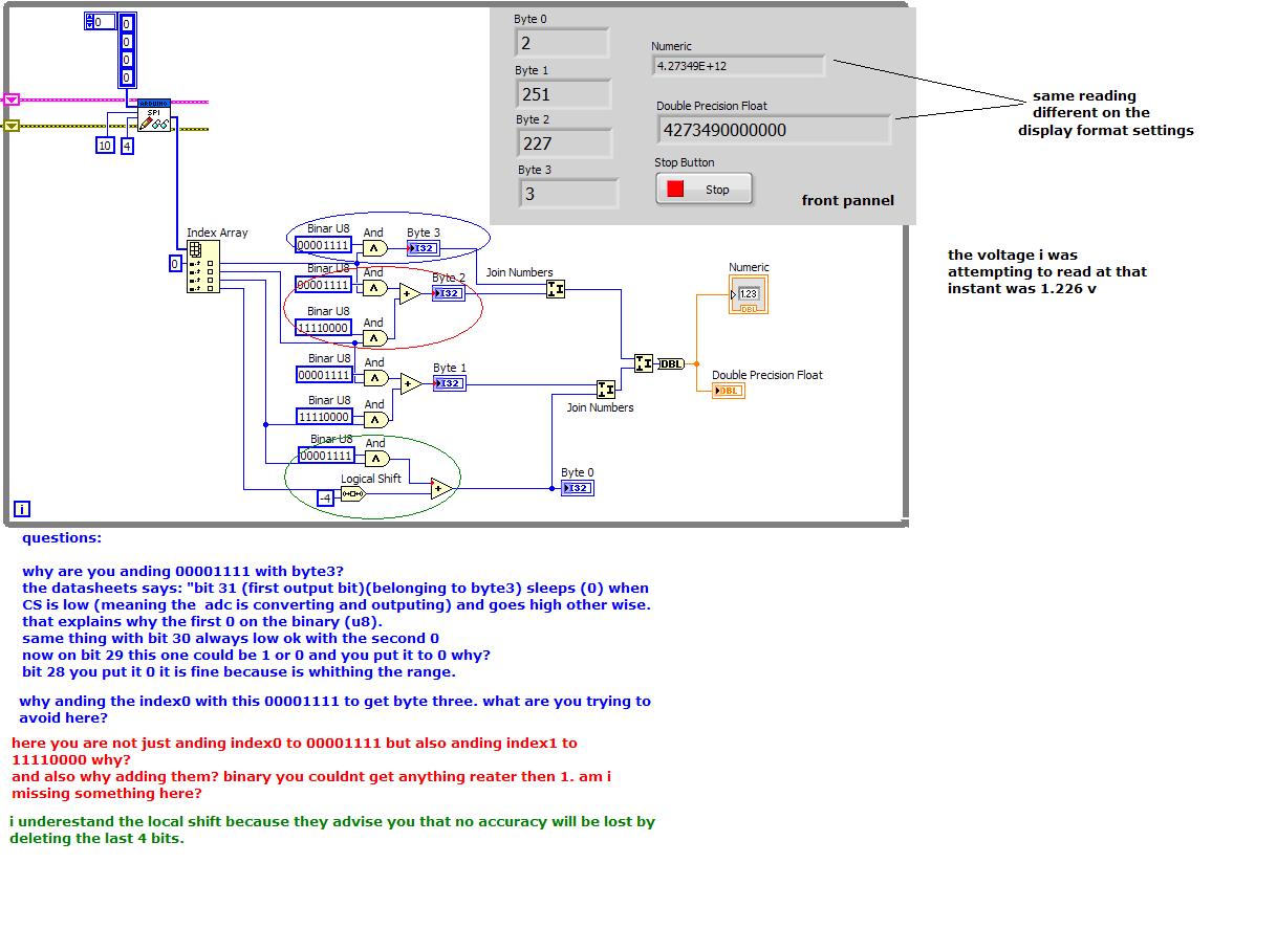
sam,
the number i get is absurd (713915000) and i have 3.3v.
here is what i believe, since the spi config am using is msb then i need to dish out a full byte; 4 bits of the 1st byte and 4 bits of the last byte.
how can i acomplish this?
12-08-2011 01:39 PM
- Mark as New
- Bookmark
- Subscribe
- Mute
- Subscribe to RSS Feed
- Permalink
- Report to a Moderator
Caluctra,
What do you mean by dish out? Is the devicre returning a 32-bit double?
-Sam K
LIFA Developer
12-08-2011 01:43 PM
- Mark as New
- Bookmark
- Subscribe
- Mute
- Subscribe to RSS Feed
- Permalink
- Report to a Moderator
Caluctra,
Alright lets try this again. My original post was nonsense. This is a bit more complicated and I really don't like the format that this sensor returns data in. It involves a bit more bit shifting, but isn't too bad. I've attached the code this time as well.
Let us know if this helps.
-Sam K
LIFA Developer
12-09-2011 08:36 AM
- Mark as New
- Bookmark
- Subscribe
- Mute
- Subscribe to RSS Feed
- Permalink
- Report to a Moderator
Sam,
Iam still unsuccesfull in reading the value although the readings cut by half. there is no decimal point on the reading, and keeps being a huge number compare with the actual value.
iam attaching a .jpeg file with some questions.