- Document History
- Subscribe to RSS Feed
- Mark as New
- Mark as Read
- Bookmark
- Subscribe
- Printer Friendly Page
- Report to a Moderator
- Subscribe to RSS Feed
- Mark as New
- Mark as Read
- Bookmark
- Subscribe
- Printer Friendly Page
- Report to a Moderator
Wireless DAQ - Continuous Analog Input with Network Error Handling
Overview
This example is designed to show how to acquire hardware timed continuous analog data from WLS-9xxx devices and recover from errors that might happen due to network lag or events. The concept of error handling MUST exists in wireless applications because there is always a chance for communication loss.Some examples of this are other wireless networks that are on the same wireless channel as the WLS-9xxx network or Bluetooth devices that are in very close proximity to a WLS-9xxx device. These types of events and errors can be accounted for in software. The best and easiest way to do this is once an error has been identified at the DAQmx Read function, stop then clear the DAQmx task. This will put the DAQmx driver on the host computer back in a known error free state and then a small programing delay of 1 or 2 seconds to allow the WLS device to also clear its resources. Now a new DAQmx task can be configured with the same settings as before. If another error is encountered keep clearing and re configuring until a good connections is established or network lag/event is over. If a lot of errors are seen in a short amount of time simply change the wireless channel of the router or access point to try to improve data throughput.
Wireless Streaming Explained
So what does 54 Mbit/s of streaming really mean when we talk about wireless G 802.11 networks?
The theoretical MAX of a wireless G network is 54 Mbits/s or ~ 6.4 MB/s of data streaming. This assumes a perfect wireless environment and since no wireless environment is perfect it is almost fair to say to cut that number in half to ~3MB/s. Now if you add security and multiple clients you can cut that number down again.
When using a WLS-9215, its max rate is 100,000 S/s/Ch. The 9215 is a 16 bit analog input module so that means:
100,000 Samples * 2 bytes * 4 Chs = .8 MB/s or 6.7 Mbits/s max streaming rate. With that amount of data a good application could sustain 2 - 3 WLS-9215s connected and streaming at full rate to a single wireless G router.
To put these numbers in perspective, Speedtest.net reports that the average U.S. household Internet downlink bandwidth is 6.17 Mbps. In other words, one NI Wi-Fi DAQ device can stream more data than your home Internet connection is capable of handling.
System Diagram
The WLS-9xxx device should be connected in the following way for Infrastructure Mode:
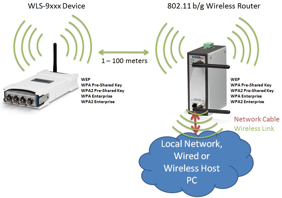
Note: If your WLS/ENET DAQ device is wireless and your host PC is wireless this will be effectivily doubling the data being sent over the wireless air space. This will have an affect on how much data you will be able to stream because you are having to send the data twice through the air, WLS-9xxx >>wireless>> G Router >>wireless>> Host PC. To maximize throughput connect your host PC to the router or network via ethernet cable.
LabVIEW Applicaiton's
There are two different LabVIEW applications attached to this document. One will show how to use a state machine run application to determine the environment quality by displaying errors and the time of the errors to the user. The other will be an example of how WLS DAQ can be programmed in a development or deployment application using a simple one loop archetecture. The following is needed to use these LabVIEW applications:
1.Install DAQmx 8.9 or greater
2. Make sure you have followed the NI-DAQmx WLS-9163 Getting Started Guide
3. Upgraded the firmware of the WLS-9163 to 2.0.0. In January of 2010 National Instruments implemented some new techniques to help the WLS-9163 in poor wireless environments.
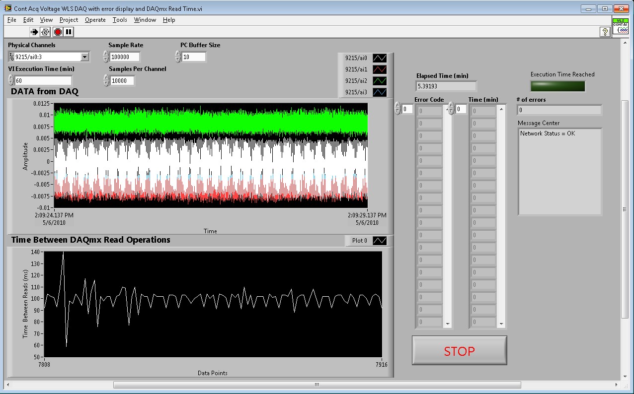
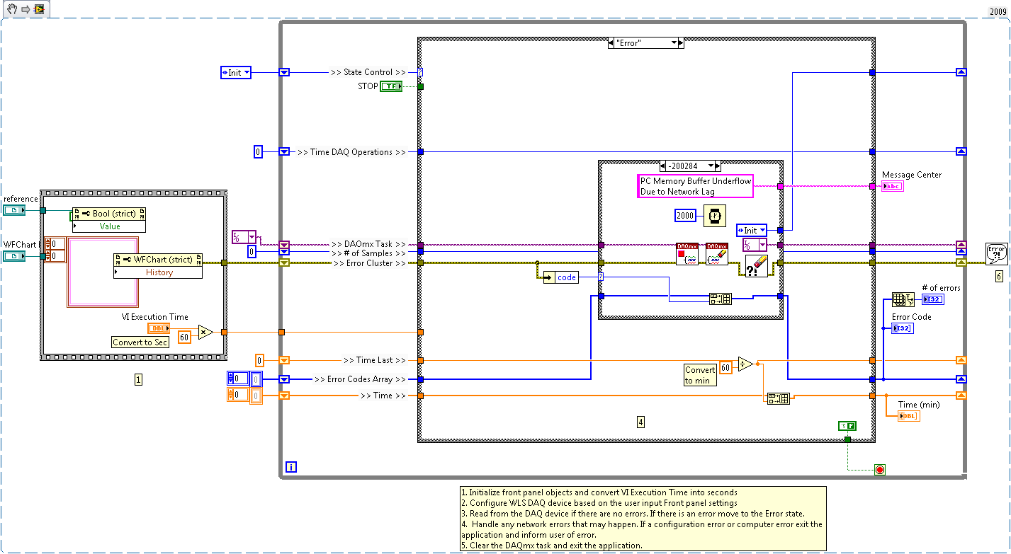
Application 1 - Environment Test Application
The biggest concern in a wireless application is how will the environment affect the performance of my application. Sometimes network analyzing tools are hard to come by so one way to check the environment is to use an application that can display how many network errors happen in a given time frame. This VI uses a state machine to go between initialize, error and read states. The front panel also makes use of indicators to show data, time between DAQmx operations, number of errors, error numbers, the time a specific error occurred, message center with information about errors happening and the time the VI has been running. Simply set the VI Execution Time and then see how many errors happened during that amount of time. If there are more than desired simply change the wireless channel and or WLS-9xxx device location until the errors stop.
Environment Test Applicaiton Front Panel
Environment Test Application Block Diagram (NOTE: Picture below is a VI snippet.)
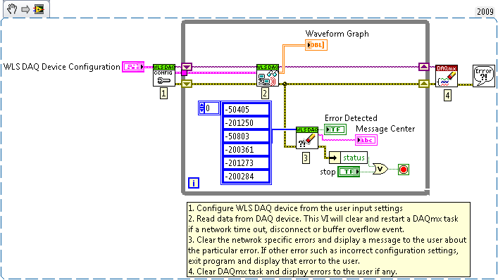
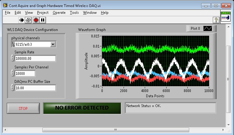
Application 2 - Development or Deployment Application
This application is an example of how the DAQmx driver can be used to collected data from a development or deployment application using a simple one loop architecture. The VI accounts for network errors that may occur such as network time out or buffer overflows due to network lag. If post processing or data logging is needed simply use a producer consumer architecture to accomplish this. This will allow the Producer loop to execute faster after a network lag event has occurred.
Development or Deployment Applicaiton Front Panel
Development or Deployment Application Block Diagram (NOTE: Picture below is a VI snippet.)