- Subscribe to RSS Feed
- Mark Topic as New
- Mark Topic as Read
- Float this Topic for Current User
- Bookmark
- Subscribe
- Mute
- Printer Friendly Page
A timing error Occurred... HELP!
05-07-2014 09:58 PM
- Mark as New
- Bookmark
- Subscribe
- Mute
- Subscribe to RSS Feed
- Permalink
- Report to a Moderator
I was trying to build a simple program where I read the simultaneous AI and write the value to a FPGA to Host type User-defined Variable and then plot the values in a different VI within the "My Computer" target. But I keep getting an error that reads "A timing error occured" when I try to compile it. Could someone tell me what I am doing wrong and I to handle such cases? I have attached the project, and the VIs that I used and also screenshots of the errors.
I was able to run this program the first time then I tried to add a user defined variable to have a common stop button for both the VIs but now nothing works. Even a simple straight forward project like the one I have attached here will not compile.
Any help and assistance would be greatly appreciated!
05-12-2014 02:53 PM
- Mark as New
- Bookmark
- Subscribe
- Mute
- Subscribe to RSS Feed
- Permalink
- Report to a Moderator
Sorry for the slow reply. It looks like you are trying to use a shared variable to transfer data between the FPGA and the Real-Time Host processor. This is a feature that is only supported when usin the NI Scan Engine. (Scan Mode is a way of accessing I/O modules on CompactRIO chassis without programming the FPGA using a single-point interface suitable for low speed control applications like 100 Hz control loops.) However, the sbRIO-9606 and GPIC do not support Scan Interface mode. If you check the Chassis configuration, you'll see that it's configured for LabVIEW FPGA Interface mode. That means that you will be programming the FPGA like a normal reconfigurable FPGA target, which is what you want for programming power converter control applications.
It looks like you are reading a simultaneous analog input channel on the GPIC. Do you want to read it at a high speed like an oscilloscope (waveform streaming) or do you want to access the most recently single data point for a control algorithm located on the RT processor?
Assuming it's the latter (you want to access the most recent analog input value to close a control loop on the VxWork real-time processor), you would modify the FPGA application like this:
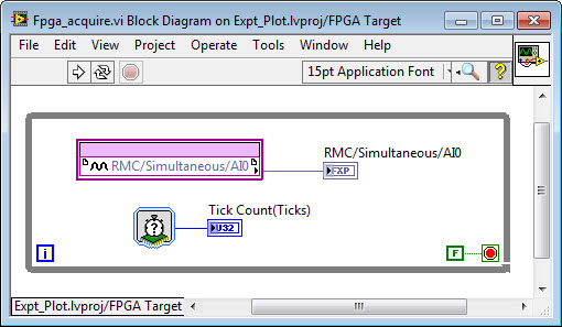
As you can see, the analog input channel is being written to a front-panel indicator register of the FPGA application. The RT application can then access it in a control loop. (I also included a Tick Count subVI to provide a timestamp.) Hit the Run button to start the FPGA VI compiling.
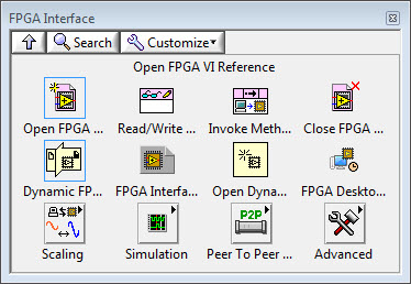
To create a LabVIEW Real-Time application to read the analog input, right click on the NI-sbRIO9606 in the project and select New>VI. Then right-click on the block diagram and navigate to the FPGA Interface palette. Drop down the Open FPGA VI Reference function, right-click to configure it, and select your FPGA VI by name ("Fpga_acquire.vi").
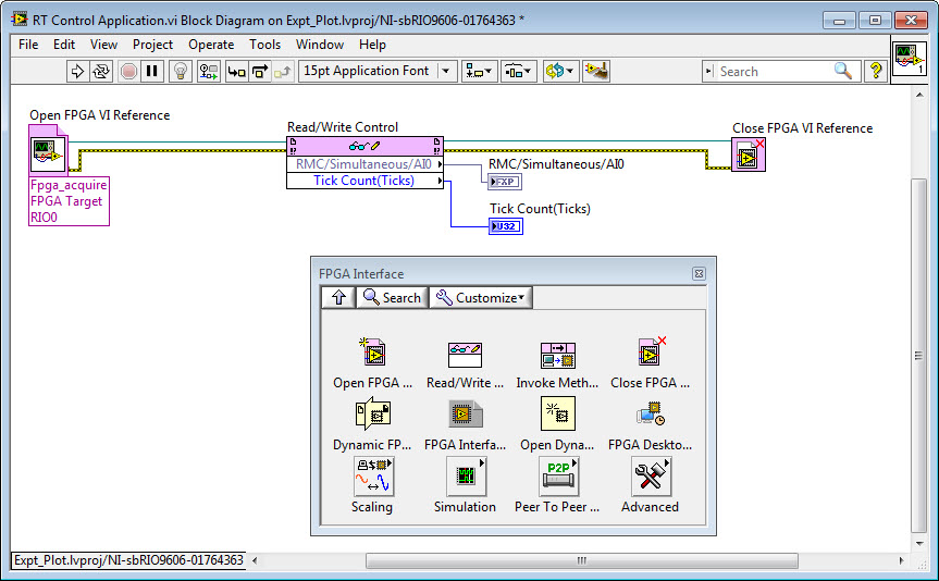
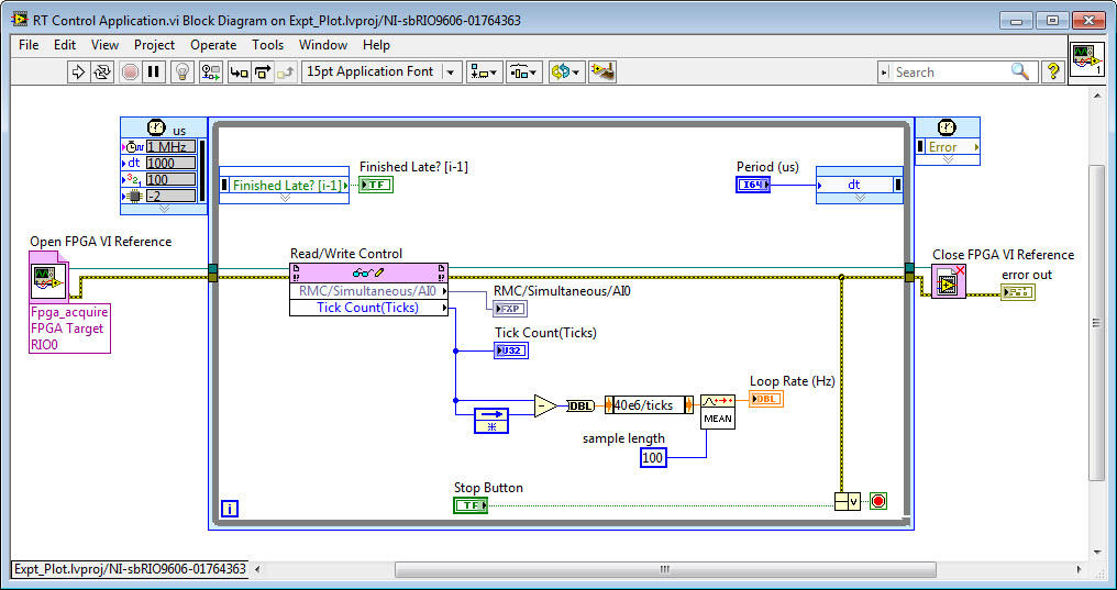
Next drop down the Read/Write Control function. Wire the FPGA VI Reference Out and Error Out signals to it. Then left-click on Unselected and choose the name of the FPGA front panel controls/indicators you want to access from your real-time processor control loop. In this case, I've selected RMC/Simultaneous/AI0 and then dragged down to add Tick Count(Ticks). Then right-click on those terminals and create indicators for the front panel of the RT application. Next add a Close FPGA VI Reference function and wire it up. At this point, your RT control application should look like this:
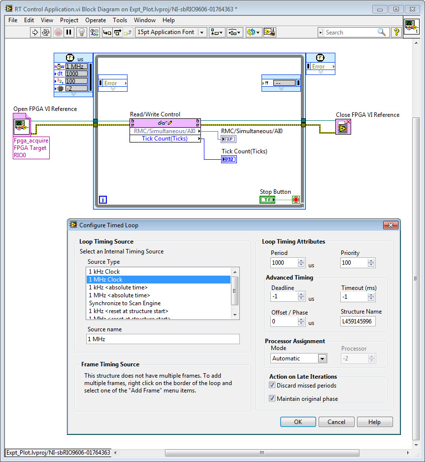
Now, assuming you are doing real-time control in this application, you'll want to drop down a Timed Loop structure around your Read/Write Control function. You can find this on the palette under Programming>Structures>Timed Structures>Timed Loop. Then double click the left ear of the timed loop and configure it. Set it to use the 1 MHz Clock rather than 1 kHz Clock. Then if the period is set to 1000 us, the period of the loop on the real-time operating system will be 1 millisecond (1 kHz). All of the code contained inside the Timed Loop structure will be executed at time critical priority on the VxWorks real-time operating system. In this case, the Priority is set to 100. The number only matters in comparison to the priority of other timed loops. If you have multiple Timed Loops, the one with the highest Priority will preempt the execution of lower priority loops. Each Timed Loop automatically sleeps when completed, allowing lower priority tasks to execute. If there is not enough sleep time for the lower-priority tasks (such as Ethernet networking) to execute, they will be "starved". Therefore, on a real-time operating system it's important to make sure the high priority tasks are not consuming too much of the processor resources.
Finish out your RT application by adding some logic to analyze the loop rate in Hz by reading the 40 MHz FPGA clock value (Tick Count), and control and monitor the loop rate using features of the RT Timed Loop structure. Summary: Added Feedback Node (Programming>Structures) and right-clicked on it to Change Direction. Subtracted the most recent Tick Count(Ticks) from the value on the previous iteration (Programming>Numeric>Subtract). Converted the time interval from an Integer to Double Precision (Programming>Numeric>Conversion). Used an Expression Node to convert the time interval from 40 MHz ticks to Hz using the equation Loop Rate (Hz) = 40e6/ticks (Programming>Numeric>Expression Node). Computed the Mean Loop Rate over the last 100 iterations (Signal Processing>Point-by-Point>Prob & Stat>Mean PtByPt). Also, OR'd the Stop Button with the error cluster so the loop will stop if an error occurs (Programming>Boolean>Compound Arithmetic), and created an error out indicator. Created a control for the loop period wired to the right inner ear of the Timed Loop, and an indicator for Finished Late? [i-1].
Here is the completed application running.
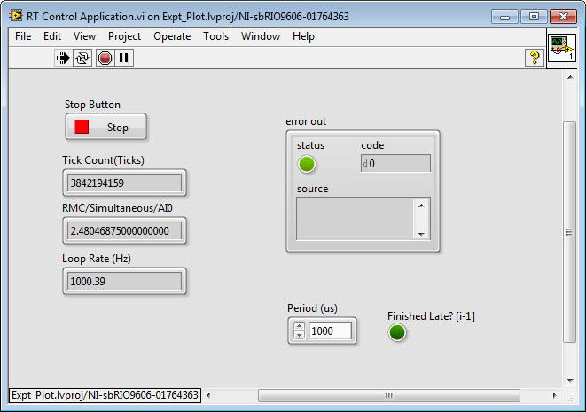
In this case, I can run the time critical control/analysis loop at rates up to 5000 Hz (200 us), while reserving sufficient processor time when the time critical Timed Loop is sleeping for lower priority tasks to run.
The code is attached.
If you are looking for an example showing oscilloscope like high speed data streaming, see the new GPIC Reference Design Code (requires LabVIEW 2013 SP1 or higher).
Please let me know if this information is helpful.
You might also be interested in these short RIO programming tutorial videos (Develop an Embedded System in 10 Minutes), an NI RIO Evaluation Kit, and/or attending a Build Your Own Embedded System Workshop.
05-13-2014 01:21 PM
- Mark as New
- Bookmark
- Subscribe
- Mute
- Subscribe to RSS Feed
- Permalink
- Report to a Moderator
The project file "Power Electronics Design V Hands On Workshop.lvproj" seems to be missing in the "Hands on Exercise" folder in the GPIC Reference Guide Folder...??
05-13-2014 01:56 PM
- Mark as New
- Bookmark
- Subscribe
- Mute
- Subscribe to RSS Feed
- Permalink
- Report to a Moderator
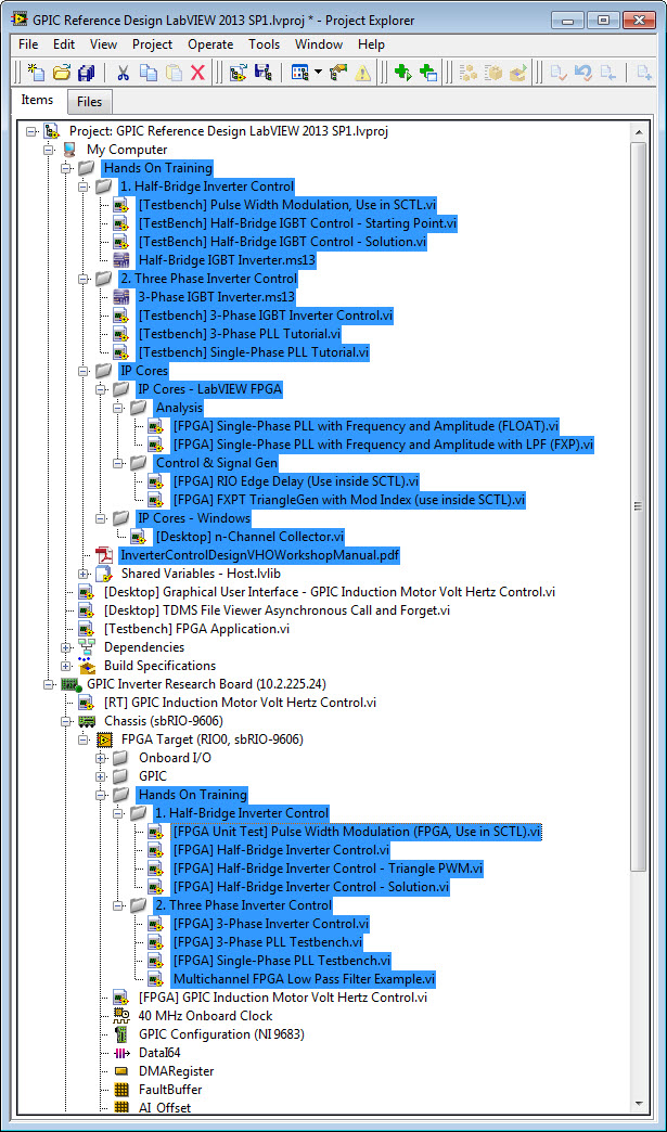
I'm not following you. The new GPIC Reference Design Code (requires LabVIEW 2013 SP1 or higher) contains the power electronics design V hands on exercise examples, located in a folder named "Hands On Training." That ZIP file does not contain a project file with the name you gave.
In the screenshot below, I've highlighted the locations of the hands on training files that are included in the new GPIC reference design project. Note that the hands on workshop manual still needs to be updated to reference the new location of the files in the project.
05-13-2014 02:21 PM
- Mark as New
- Bookmark
- Subscribe
- Mute
- Subscribe to RSS Feed
- Permalink
- Report to a Moderator
Oh! I think I get it! Thanks!
And also thanks for the elaborate response to my first query. The response was worth the wait!
