- Subscribe to RSS Feed
- Mark Topic as New
- Mark Topic as Read
- Float this Topic for Current User
- Bookmark
- Subscribe
- Mute
- Printer Friendly Page
Current Probe limitations in Cosimulation
09-09-2012 10:54 PM
- Mark as New
- Bookmark
- Subscribe
- Mute
- Subscribe to RSS Feed
- Permalink
- Report to a Moderator
Hey guys,
I have been using the Multisim and LabVIEW cosimulation tool and have found that the current probe settings does not transfer correctly to the LV cosimulation. Whenever, I set the current probe to mV/mA or V/mA it gives me the same result. I suspect since the V/mA is the default value and I am gettting pretty large values, that this is the default setting one should use when using the current probe...
Has anybody run into the same issue?
Regards,
Ahmad Zaatari
09-10-2012 12:36 AM
- Mark as New
- Bookmark
- Subscribe
- Mute
- Subscribe to RSS Feed
- Permalink
- Report to a Moderator
Ok, so as it turns out the problem was completely unrelated to the current probe. Rather, I was using a voltage controlled source and controlling the input in LV simulation. This seems to be the wrong approach since its highly dependent on the simulation loop update rate as opposed to the multisim spice engine. The best approach is to use the ABM voltage source and change the inputs as shown in the Chaos example in Brian's example code.
I was testing the circuit in Multisim and LV, and I wrongly attributed the mismatch in results to the current probe.
Lesson, it is best to use the ABM Voltage source for a sine function in cosimulation.
Regards,
Ahmad Zaatari
09-10-2012 08:26 AM
- Mark as New
- Bookmark
- Subscribe
- Mute
- Subscribe to RSS Feed
- Permalink
- Report to a Moderator
Hi Alex,
Make sure you are saving the Multisim file in between simulation runs. Also make sure you are checking the right current signals, etc. in LabVIEW.
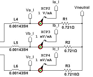
The gain settings on the current probes are respected in co-simulation. As a sanity check, I changed the current sensor gain to 1 V/mA on this SKiiP3 switching/conduction loss and transient thermal simulation. The current is provided in mA rather than Amps, therefore my chart and indicator labels are incorrect.

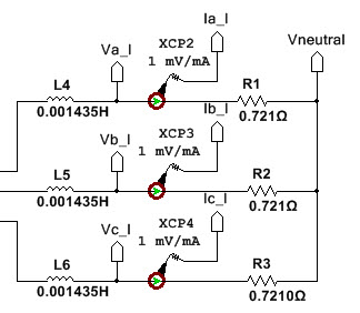
Next I change it back to a gain of 1 mV/mA and save the Multisim schematic. Now currents are provided in Amps and my chart & indicator labels are correct.
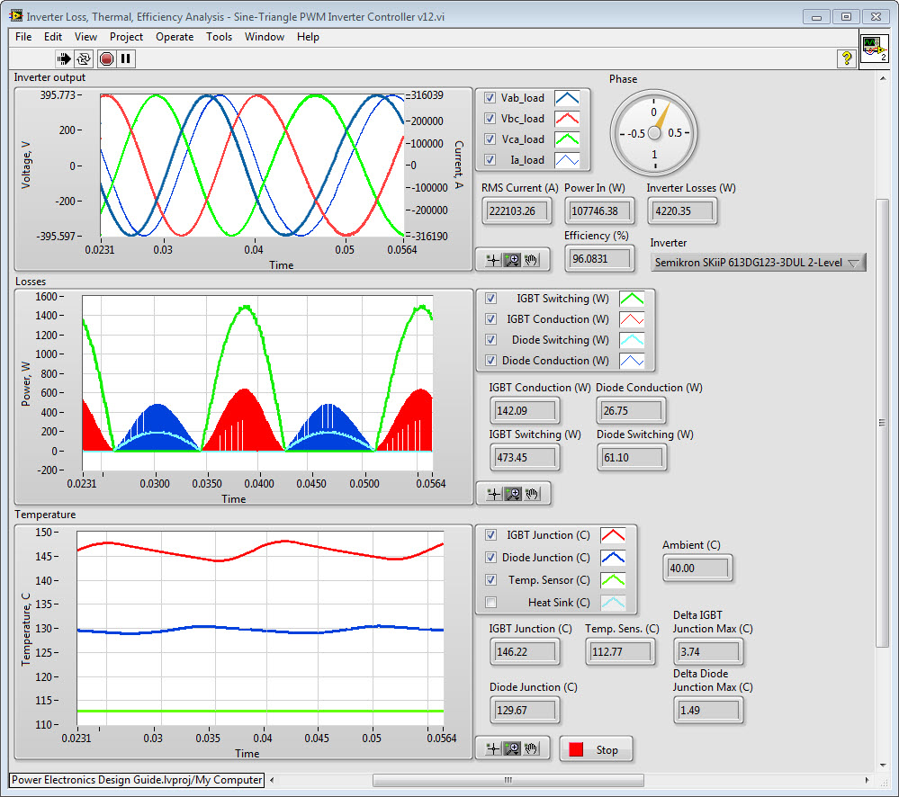
By the way, if anyone has transient thermal test data for their inverters, we are interested in providing early access to the new IGBT & diode models in development (used in the simulations above) if you are interested in helping us validate the new simulation models against your test data. The new models calculate switching/conduction losses and transient thermal response based on the exact custom pulse width modulation algorithm you develop in LabVIEW FPGA. The goal is to have a thermal & loss model that's accurate enough for developers to evaluate subtle differences between alternative control schemes, IGBT module choices and of course different converter topologies. We are also designing it so that the IGBT module parameters can be easily taken from the vendor datasheet (or physical testing if necessary), therefore you aren't dependant on the device vendor to provide a model (although we'd like to have pre-validated models for standard IGBT choices). If anyone is interested in joining the beta program to help us validate a device model by comparing it to their physical inverter, please email me (brian.maccleery@ni.com).
Cheers,
BMAC
09-10-2012 08:29 AM
- Mark as New
- Bookmark
- Subscribe
- Mute
- Subscribe to RSS Feed
- Permalink
- Report to a Moderator
Hi Ahmad,
I tried this out, but things seem okay for me.
The Multisim schematic uses two current problems (on the same signal) with different scales.
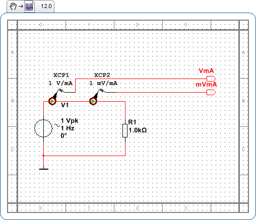
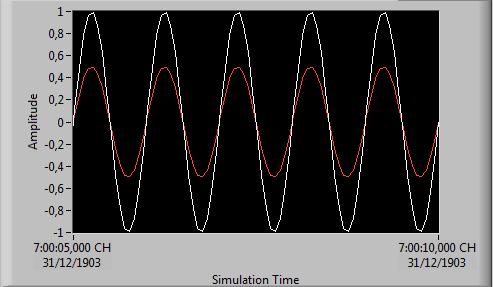
In LabVIEW, I scale one of them up so they appear nice on the graph
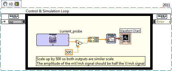
The output is exactly what I expect
If possible, could you post your files so I can see if there is something special about your design.
Senior Software Developer
National Instruments
Circuit Design Community and Blog
If someone helped you, let them know. Mark as solved or give a kudo. 🙂
