- Subscribe to RSS Feed
- Mark Topic as New
- Mark Topic as Read
- Float this Topic for Current User
- Bookmark
- Subscribe
- Mute
- Printer Friendly Page
- « Previous
-
- 1
- 2
- Next »
How to simulate the temperature, energy efficiency and lifetime of power electronics transistors in co-simulation?
07-01-2014 06:17 PM
- Mark as New
- Bookmark
- Subscribe
- Mute
- Subscribe to RSS Feed
- Permalink
- Report to a Moderator
For the heat sink, last time, you said that if there is no transient thermal model, just use a simple resistor to represent the thermal impedance. I have a question here. What is the relationship between the resistance and the thermal impedance? 1ohm means 1C/W? Thanks.
07-02-2014 07:31 PM
- Mark as New
- Bookmark
- Subscribe
- Mute
- Subscribe to RSS Feed
- Permalink
- Report to a Moderator
You are exactly right. A 40 Ohm resistor would model a thermal impedance of 40 C/W.
By the way, it's relatively easy to get the thermal time constant (tau) in seconds. The time constant (tau) represents the time it takes the system's step response to reach 63.3% of its final (asymptotic) value.
.jpg)
Here's an example. Using the GPIC Reference Design Code, I connect to the sbRIO GPIC, Enable Control, turn on Datalogging on the Windows GUI application, and Enable PWM.
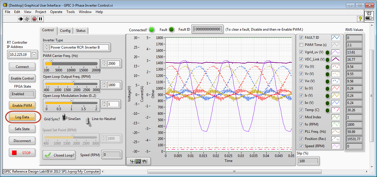
The inverter starts at ambient temperature, and begins to heat up. After it reaches steady state (about 25 minutes), I click the STOP button and the TDMS file viewer pops up to show me the log file (2.2 GBytes since I was recording at 10 kS/s. If you want a smaller file, set the RT controller to acquire at a lower rate.)
Here is the log file results for the IGBT temperature, as measured by the thermistor embedded in the 6-pack IPM.
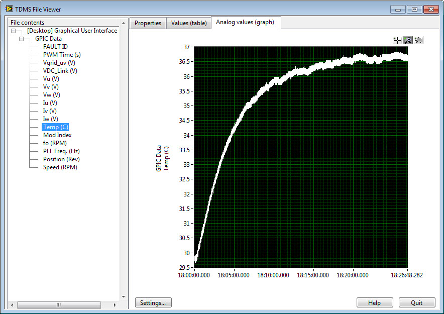
In a spreadsheet I figure out that the temperature rise is 7 C, so the temperature that represents a 63.3% rise is 34.1 C. Then I zoom in on the graph where it crosses 34.1 C and look at the time from the start to when it reaches 34.1 C. In this case, it's 290 seconds. That's the time constant, tau.
Alternately, I could run the inverter up and then disable the inverter and record the cool down. In this case, I was spinning a 3-phase induction motor which pulls more current, so the inverter got hotter.

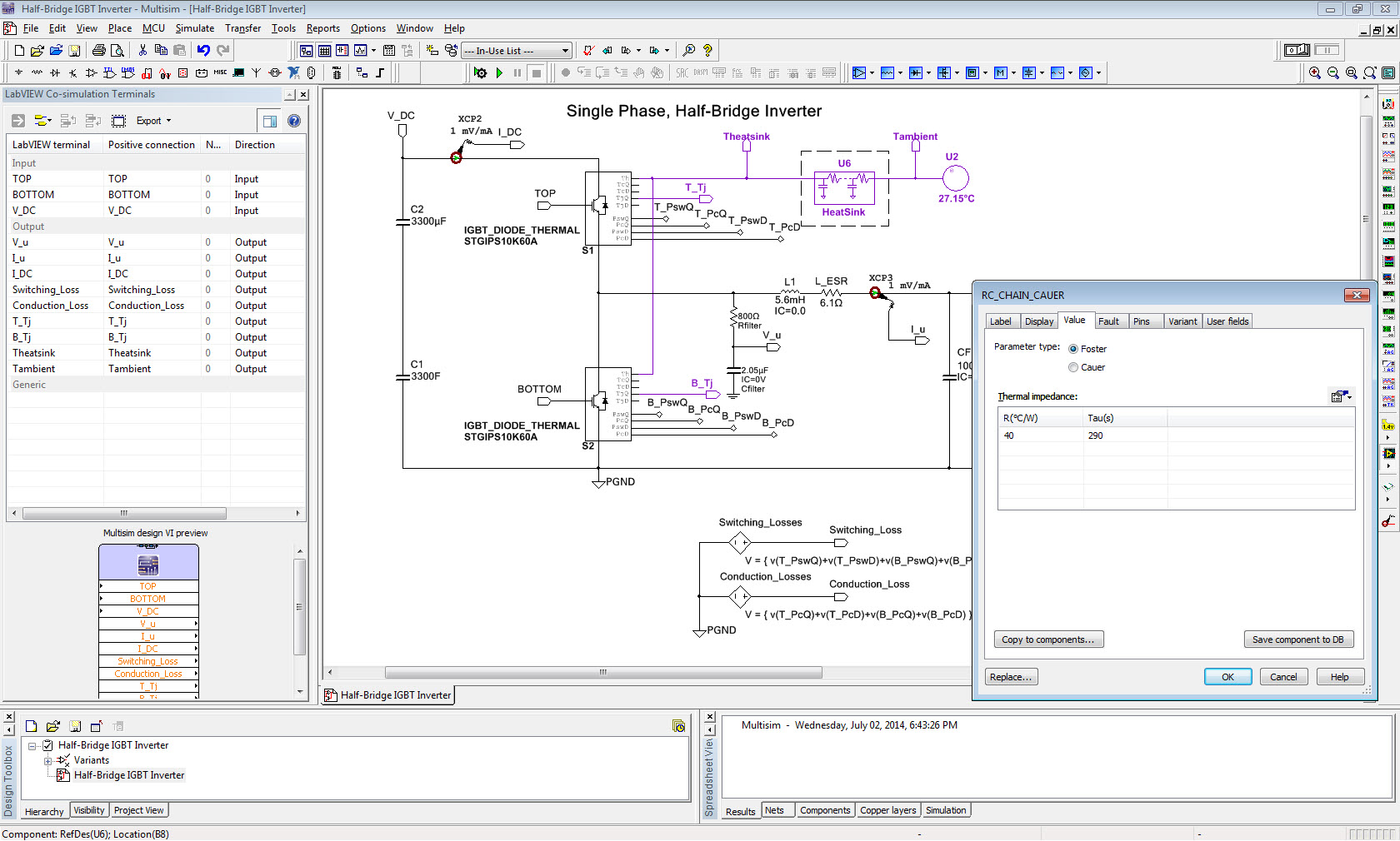
I enter the time constant (290 seconds) into the Multisim model and save the file. Now I'm ready for co-simulation with a good thermal model. I set ambient to match the starting temperature of my test data.
I run the LabVIEW FPGA/Multisim co-simulation for a few cycles to establish the steady state losses in the IGBTs. Then I start the simulation again and it initializes to the proper steady-state temperature, and the simulation shows the transient oscillations around the steady-state temperature. Beautiful!
The green trace below shows the simulated IGBT junction temperature, which starts at the same steady state value as my measurements (36.6 C), and has about 0.2 degrees of oscillation during the 60 Hz sine-triangle PWM cycle.
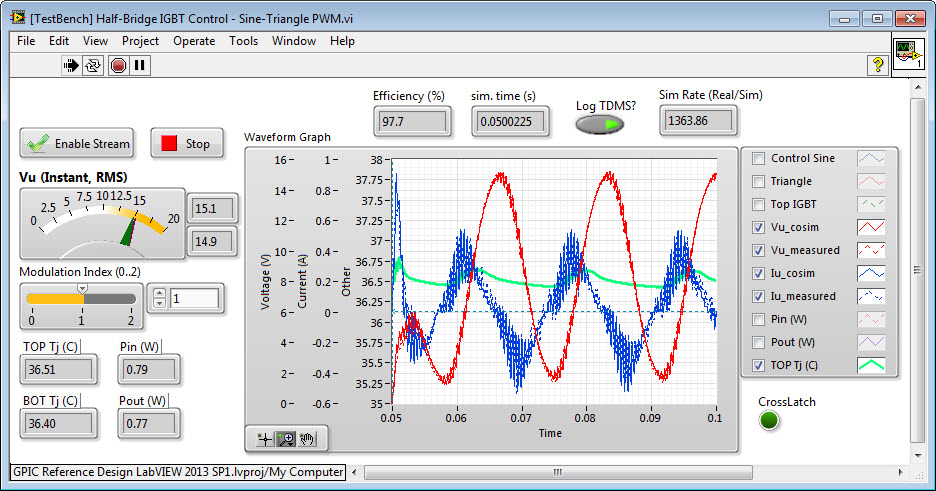
Note that the thermistor embedded in the IGBT module is not located directly at the junction of the transistor. It's some distance away in the potting compound. Thus, you should expect the simulated junction temperature to show more fluctuations than you can measure with the thermistor. (Some vendors, Fuji for example, provide a datasheet that gives both junction and thermistor transient thermal response.)
11-01-2020 10:42 AM
- Mark as New
- Bookmark
- Subscribe
- Mute
- Subscribe to RSS Feed
- Permalink
- Report to a Moderator
Hi,
I really liked your thermal model from co-simulation and wanted to try it out. I've downloaded Labview 2020 with the add on packages suggested in the instructions.
However, when I go to run the simulation I get a couple of errors.
1) The first is with the FPGA Half Bridge Control: The error message states item configured incorrectly.

2) The second error is with the Half_Bridge_Diode_Thermal.

I hoping you may be able to help me, as I have no experience of using Labview.
Kind regards,
Andy
11-09-2020 08:18 AM
- Mark as New
- Bookmark
- Subscribe
- Mute
- Subscribe to RSS Feed
- Permalink
- Report to a Moderator
Just to update anyone having a similar problem. The RT single-board RIO Target sbRIO-9606 is no longer supported in Labview 2020 and this means the FPGA cannot be selected. By deploying to a different compact RIO target such as the sbRIO-9607, the problem can be resolved.
The following shows how to do this. The parameters in the Desktop Execution Node will need to be reconfigured to the new target FPGA.
https://knowledge.ni.com/KnowledgeArticleDetails?id=kA00Z000000P6kpSAC&l=en-GB
- « Previous
-
- 1
- 2
- Next »
