- Subscribe to RSS Feed
- Mark Topic as New
- Mark Topic as Read
- Float this Topic for Current User
- Bookmark
- Subscribe
- Mute
- Printer Friendly Page
I'm measuring the 3-phase grid voltages line-to-line. What is the phase and amplitude relationship to my inverter control sine waves?
09-03-2015 04:52 PM
- Mark as New
- Bookmark
- Subscribe
- Mute
- Subscribe to RSS Feed
- Permalink
- Report to a Moderator
This is a great question and a common source of confusion, and a question that comes up all the time.
"I'm measuring the 3-phase grid voltages line-to-line. What is the phase and amplitude relationship to my inverter control sine waves?"
For grid tied inverters, it's more common to take line-to-line voltage measurements at the point of common coupling to the grid and use that for the inverter phase-lock-loop (PLL), since the neutral voltage is not always available. The goal of the inverter control system is to produce sinusoidal currents that are in phase with the grid voltage, thereby delivering unity power factor, or currents with some programmable phase shift thereby delivering the desired amount of reactive power.
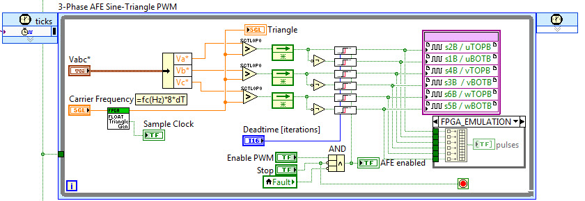
So... What is the relationship between the grid voltages measured line-to-line and the inverter control sine waves, i.e. the Vabc* cluster in the LabVIEW FPGA sine-triangle PWM block diagram below (download code)?
Sine-triangle PWM is the most classic PWM scheme and it works well. Like PID control, it's hard to beat. You compare your control waveform (Vabc*) against a triangle wave (Triangle) to modulate it. If you low pass filter (i.e. LCL) the modulated control waveform you get back the original control waveform, although there is phase shift caused by the filter.
The 3 half bridges of a 2-level, 3-phase inverter produce line-to-neutral voltages. So, for the inverter output voltages to be "in phase" these line-to-neutral control sine voltages (Vabc*) need to have a -30 degree (lagging) phase shift and 1/sqrt(3) or 0.577 amplitude relationship compared to the line-to-line voltages measured at the point of coupling to the grid.
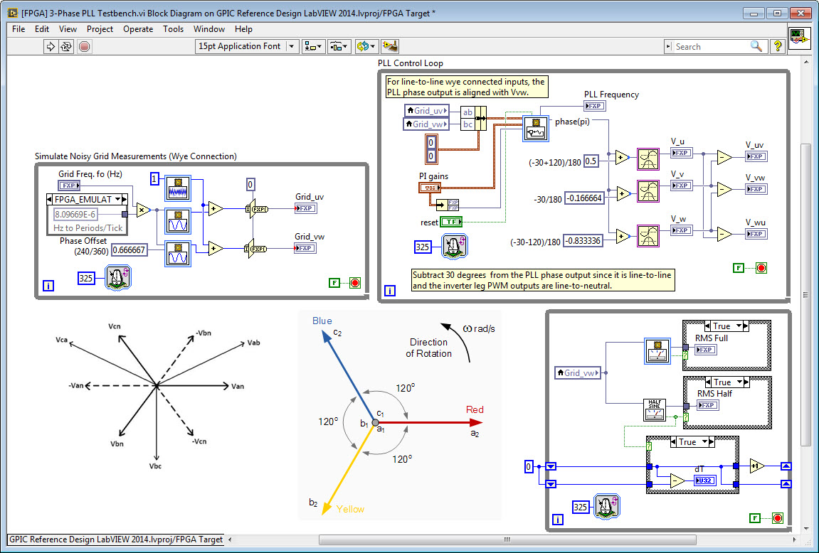
However, keep in mind that many PLL IP cores give you a phase output that is not aligned with Van, as is customary in literature. For example, if you give line-to-line voltage measurements to the 3-phase PLL that ships on the LabVIEW FPGA palette, you get out a PLL phase output that is aligned with Vbc. By the way, it's also in units of pi radians rather than radians so a value of 1 represents a positive 180 degree phase angle.
So... if your PLL is giving you a phase angle that's aligned with Vbc then what is the phase shift needed to get your sine-triangle control waveform aligned with Van?
Let me cut to the chase and give you the answer for all three phases, and then explain how I got there.
If the PLL output phase is aligned with Vbc, then add 90 degrees to get the phase for Van, add -30 degrees to get the phase for Vbn, and add -150 degrees to ge the phase for Vcn.
The solution is included in the [Testbench] 3-Phase PLL Tutorial.vi example FPGA code that's with the NI Power Electronics Design V Training Course (download code).
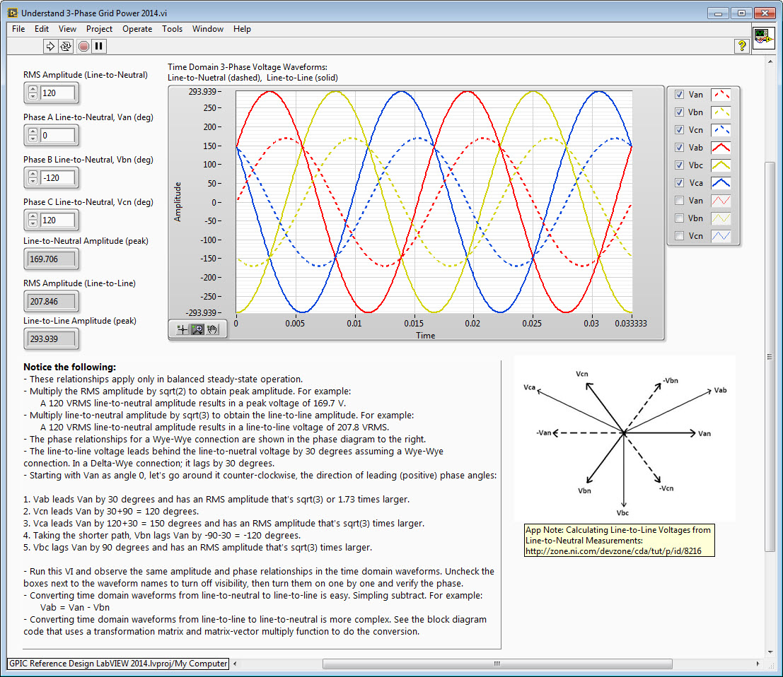
This NI app note does an okay job of explaining the Line-to-Line Voltages and Line-to-Neutral conversions... which is summarized by the phasor diagram drawing below.
Starting with Van as angle 0, let's go around it counter-clockwise-- the direction of leading (positive) phase angles:
1. Vab leads Van by 30 degrees and has an RMS amplitude that's sqrt(3) or 1.73 times larger.
2. Vcn leads Van by 30+90 = 120 degrees.
3. Vca leads Van by 120+30 = 150 degrees and has an RMS amplitude that's sqrt(3) times larger.
4. Taking the shorter path, Vbn lags Van by -90-30 = -120 degrees.
5. Vbc lags Van by 90 degrees and has an RMS amplitude that's sqrt(3) times larger.
Run the attached LabVIEW 2014 VI and observe the same amplitude and phase relationships in the time domain waveforms. Uncheck the
boxes next to the waveform names to turn off visibility, then turn them on one by one in the order above and verify the phase angles.
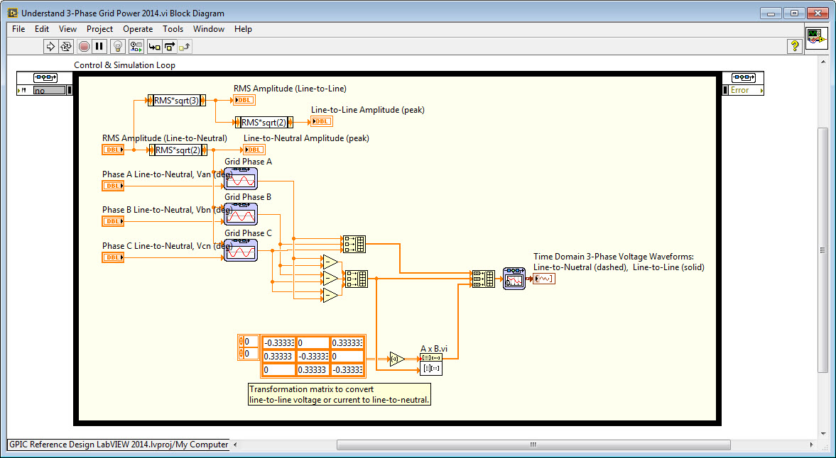
This example also shows how to convert 3-phase time domain waveforms from line-to-neutral to line-to-line (easy) and from line-to-line to line-to-neutral (hard!).
One final thing to keep in mind. The inverter line-reactor filter (most commonly LCL type) introduces phase shift as well. If your voltage and current sensors are located at the point of coupling to the grid, and you are doing field oriented control then this filter phase shift is automatically taken care of because your measurements are located after the grid. However, if you are in a situation where you do need to compensate for the line reactor filter phase shift, you can use Multisim to generate Bode plots and measure the phase shift of the filter at the synchronous grid frequency (50 or 60 Hz).
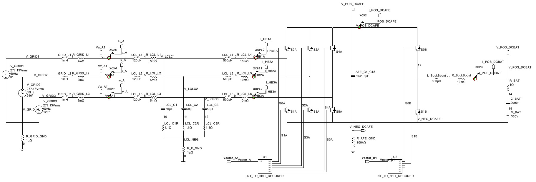
I've attached the Understand 3-Phase Grid Power 2014.vi code and grid-tied inverter Multisim model below.
BTW, if anyone finds a mistake in this post, please point it out! Thanks!
