- Subscribe to RSS Feed
- Mark Topic as New
- Mark Topic as Read
- Float this Topic for Current User
- Bookmark
- Subscribe
- Mute
- Printer Friendly Page
- « Previous
-
- 1
- 2
- Next »
Measuring single phase ac voltage in cosim
12-05-2015 01:00 AM
- Mark as New
- Bookmark
- Subscribe
- Mute
- Subscribe to RSS Feed
- Permalink
- Report to a Moderator
I tried with the below circuit and it is working fine... Negative side of the voltage is also shown
.png)
.png)
12-05-2015 12:02 PM
- Mark as New
- Bookmark
- Subscribe
- Mute
- Subscribe to RSS Feed
- Permalink
- Report to a Moderator
Hi Brian_K.
Can you help me in this? This seems to be a serious error! Even in one of the examples of NI where cosimulation of single phase inverter has been done, the output is like the one i shown you. The output is in form of pulses and not ac voltages. Please look into this problem as I am planning to take labview further in my PhD research journal.
Thanks
12-07-2015 10:00 AM
- Mark as New
- Bookmark
- Subscribe
- Mute
- Subscribe to RSS Feed
- Permalink
- Report to a Moderator
It is definitely unexpected behaviour. The strange (and difficult to report) thing is that the same code did not reporduce when I ran it on my machine. So let's see if we can get the issue to reporduce on my machine.
- What example did you use that reporduced the issue?
- What version of multisim are you using? THe complete build number would be most useful.
- What build version of labview are you using?
12-07-2015 11:21 AM
- Mark as New
- Bookmark
- Subscribe
- Mute
- Subscribe to RSS Feed
- Permalink
- Report to a Moderator
1. Please find the attachment which is the example file from NI. It has only positive voltages at the output.
2. Multisim2014
3. Labview2014
12-07-2015 02:30 PM
- Mark as New
- Bookmark
- Subscribe
- Mute
- Subscribe to RSS Feed
- Permalink
- Report to a Moderator
In response to your original post...
Multisim is giving the expected result. There is no error here. In the first code you uploaded, you were only measuring the voltage at the top of the load resistor. You should measure the voltage across the load resistor.
To do this in co-simulation, add another hierarchical connector (Ctrl-I), change the direction to Output, and connect it to the negative terminal of the load. Then in the LabVIEW Co-Simulation Terminals window, select that connector for use as the negative terminal voltage reference. In this case I labelled it "Load_neg".
You also did not have a ground in the circuit. You always need at least one ground reference and you should never leave nets completely floating. These updates are highlighted below. The updated file is also attached.
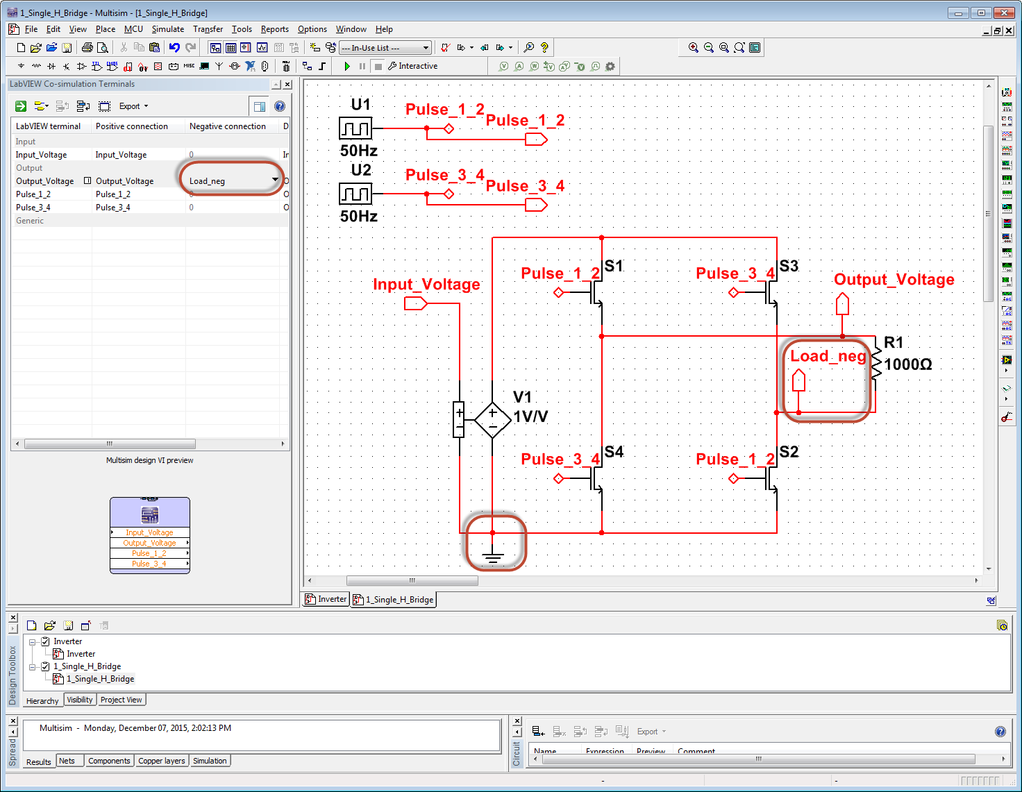
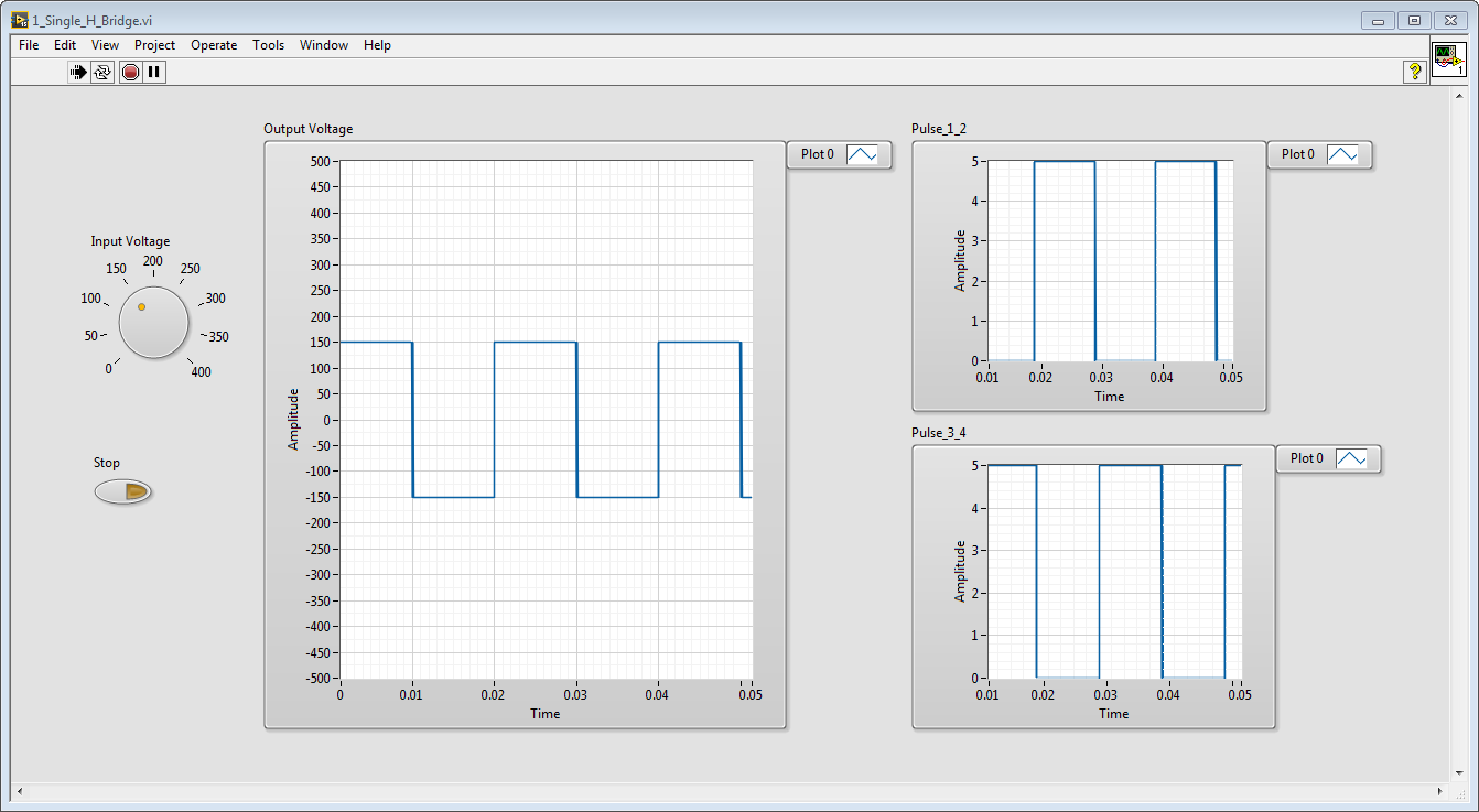
Now the expected bi-polar full bridge output voltage waveform is demonstrated.
Note: I also updated your interactive simulation settings by loading in the attached .dat file. To do this in Multisim go to Simulate>Load Simulation Settings. The default simulation settings are intended for microelectronics simulations and are not appropriate for switched mode power conversion simulation. The .dat file with recommended simulation settings is is attached.
12-07-2015 02:57 PM
- Mark as New
- Bookmark
- Subscribe
- Mute
- Subscribe to RSS Feed
- Permalink
- Report to a Moderator
This reply is in response to your post of Dec 7, 2015 11:21 AM in which you uploaded Inverter.7z...
The circuit simulation is giving the expected result. This is a half-bridge (rather than a full bridge circuit), so when the top switch (P channel MOSFET) is closed the Vout is equal to V1 minus the forward voltage drop and on-resistance of the upper transistor plus the forward voltage drop and on-resistance of the lower transistor. When the bottom switch (N channel MOSFET) is closed the Vout is equal to 0 plus the forward voltage drop and on-resistance of the lower transistor.
Therefore when the upper switch is conducting, Vout is approximately 10 Volts and when the lower switch is conducting, Vout is approximately 0 Volts (neglecting forward voltage drops and on resistances.)

Note that in this Multisim model the blue colored components indicates that you are using a detailed physics based simulation of the ON Semiconductor NTA4151PT1G Small Signal MOSFET 20V 760mA 360 mOhm Single P-Channel SC-75 with ESD Protection and NTK3043NT1G Small Signal MOSFET 20V 285mA 3.4 Ohm Single N-Channel SOT-723 with ESD Protection.
Multisim includes thousands of detailed physics based power electronics component simulation models that we've added in collaboration with the device vendors like Infineon and ON Semiconductor. Be aware that using physics based transistor models is quite different than using ideal switch models (Components>Power>Switches), which turn on and off discretely at the exact Transistor on voltage value you define.
For example, with physics based vendor models:
1. You need to include a gate resistor per manufacturer datasheet recommendations and,
2. You need to use a floating voltage controlled voltage source to properly bias from gate to drain
As an example of how to implement 1 and 2, see this buck converter example below (also attached).
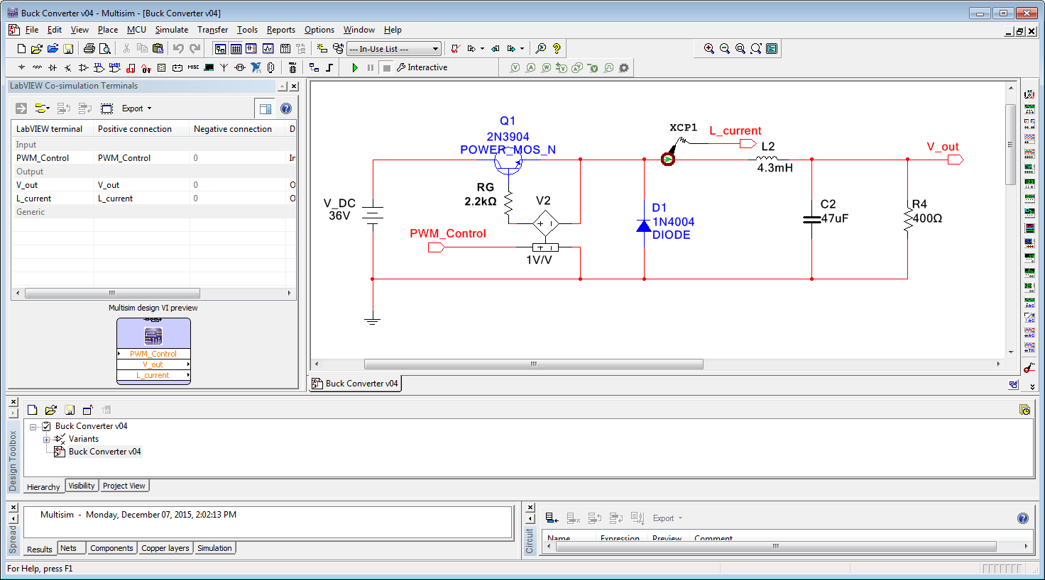
(In the Inverter.ms14 example you attached, recommendations 1 and 2 were neglected to demonstrate the handling of Multisim step size rejection and step-size negotiation that occurs between Multisim and LabVIEW during co-simulation.)
12-08-2015 01:09 AM
- Mark as New
- Bookmark
- Subscribe
- Mute
- Subscribe to RSS Feed
- Permalink
- Report to a Moderator
Thanks a lot!!
12-08-2015 01:16 AM
- Mark as New
- Bookmark
- Subscribe
- Mute
- Subscribe to RSS Feed
- Permalink
- Report to a Moderator
Thank you... Issue resolved! By the way, I have posted one more question in a new discussion. I am having problem with measuring both current and voltage waveform in a single tektronics oscilloscope. Can you resolve it?
Thanks
- « Previous
-
- 1
- 2
- Next »
