- Subscribe to RSS Feed
- Mark Topic as New
- Mark Topic as Read
- Float this Topic for Current User
- Bookmark
- Subscribe
- Mute
- Printer Friendly Page
NI Power Electronics Control Design V Training Course
09-07-2015 08:07 PM
- Mark as New
- Bookmark
- Subscribe
- Mute
- Subscribe to RSS Feed
- Permalink
- Report to a Moderator
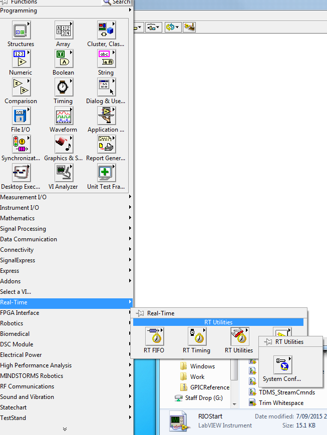
Thanks for your help. I tried to access the RT Utilities palette but I could not find the items as shown below.
I am pretty new to Labview and NI product so could you please give me some advice on this problem?
09-07-2015 08:55 PM
- Mark as New
- Bookmark
- Subscribe
- Mute
- Subscribe to RSS Feed
- Permalink
- Report to a Moderator
Hi,
Eventually, I used 'find VIs on disk' under tools and successfully located the vi (As shown below).
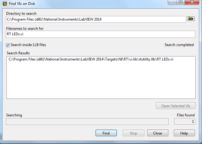
However, I still could not find it on palette. I feel very confuesd about that.
Thanks and best regards,
Zihao
09-08-2015 03:27 AM
- Mark as New
- Bookmark
- Subscribe
- Mute
- Subscribe to RSS Feed
- Permalink
- Report to a Moderator
You are accessing the RT Utilities palette on a VI that is not under an RT target. You need to have a project structure that looks a bit like this:
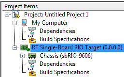
The VIs that you create under an RT target, RT Single-Board RIO Target in this case, should have the palette I showed on my previous message. The VIs that you create under My Computer will have the palette you showed.
If you are new to LabVIEW, I recommend browsing through the help which might clarify some concepts (i.e. check this page describing the components of a real-time system in LabVIEW).
09-26-2015 04:57 PM
- Mark as New
- Bookmark
- Subscribe
- Mute
- Subscribe to RSS Feed
- Permalink
- Report to a Moderator
Hello Brian,
Thank you very much for your detailed reply regarding my post earlier. That has really helped me with the IP cores and correct VIs to approach to. I must say, the algorithms developed for these boards are highly impressive and has really helped me to learn a lot.
Currently, as i mentioned earlier, am working with the DC to AC 3-phase inverter control. and here I am only working with the induction motor control on inverter A of the GPIC board.
I am still having some problems understanding and implementing the SVPWM method on this control. I have bought the NI softmotion module and have the space-vector modulation technique in it. I want to know what am i replacing in the DC-AC 3-phase inverter control.vi to work as the SVPWM rather thn as simple PWM.
For a student like me, with limited resources and knowledge, it is very confusing on how many things we need to look into in order to work with this.
I would really appreciate if i could get any feedback on this from anyone who is following this group.
Thank you and hope u have a good weekend.
Ammar Surti
09-28-2015 08:07 AM
- Mark as New
- Bookmark
- Subscribe
- Mute
- Subscribe to RSS Feed
- Permalink
- Report to a Moderator
Hi Ammar.
I looked into using the SoftMotion module to do SVPWM, but I think there is too much there to make it worth using if all you need is SVPWM. Instead I made my own which we are evaluating to see if we want to release inside a reuse package. It was made in LV2015 for a 9607 target. I have included the LV2014 code if you don't have 2015. If you don't have the drivers for the 9607 targets don't worry, all you need to do is open the VI SVPWMTestHarness.vi. If you want to compile it you will need to bring it under an FPGA target. There is only two VIs you need to get to know. One is the Core.vi inside the SVPWM library. This is the core that actually generates the boolean signals to turn the IGBTs on and off. The other is the CalcParams.vi inside the SVPWMInterface library. This calculates the configuration for the core. I hope that helps.
ftp://ftp.ni.com/outgoing/SVPWM2014.zip
ftp://ftp.ni.com/outgoing/SpaceVectorPWM.zip
09-28-2015 04:34 PM
- Mark as New
- Bookmark
- Subscribe
- Mute
- Subscribe to RSS Feed
- Permalink
- Report to a Moderator
I've also been looking into this recently and found the attached implementation guide. I think it is a more pure version of the implementation but its a bit more complex and costly to implement. I created a desktop-only implementation but I never bothered translating to FPGA. I'd go with Brian's option unless you find you need something better.
09-28-2015 04:38 PM
- Mark as New
- Bookmark
- Subscribe
- Mute
- Subscribe to RSS Feed
- Permalink
- Report to a Moderator
Thank you Brian and SmithD.
Brian, I will get back to you after trying out your approach.
Smithd, can u please share your desktop implementation on the svpwm. I would like to look at it and try it out with the sbRIO 9606 board.
09-29-2015 06:02 PM
- Mark as New
- Bookmark
- Subscribe
- Mute
- Subscribe to RSS Feed
- Permalink
- Report to a Moderator
I've just gone back and looked at it and I don't think its in good enough shape to feel comfortable posting it. The current big issue seems to be some sort of weird phase offset in the output but the code is really just not comprehensible right now without going back and forth to that PDF. If I have some time in the near future to improve it I will, but for now its really not going to be helpful to anyone.
10-02-2015 01:10 AM
- Mark as New
- Bookmark
- Subscribe
- Mute
- Subscribe to RSS Feed
- Permalink
- Report to a Moderator
Hi Brian,
Thanks for your efforts on the tutorial.
I have a problem when I tried to implement Excersice 6 (Comparing Simulated vs. Experimental Results). I run the '[RT] GPIC 3-Phase DC-to-AC Inverter Control.vi' on the RT target, but the waveform is like what the images show below.
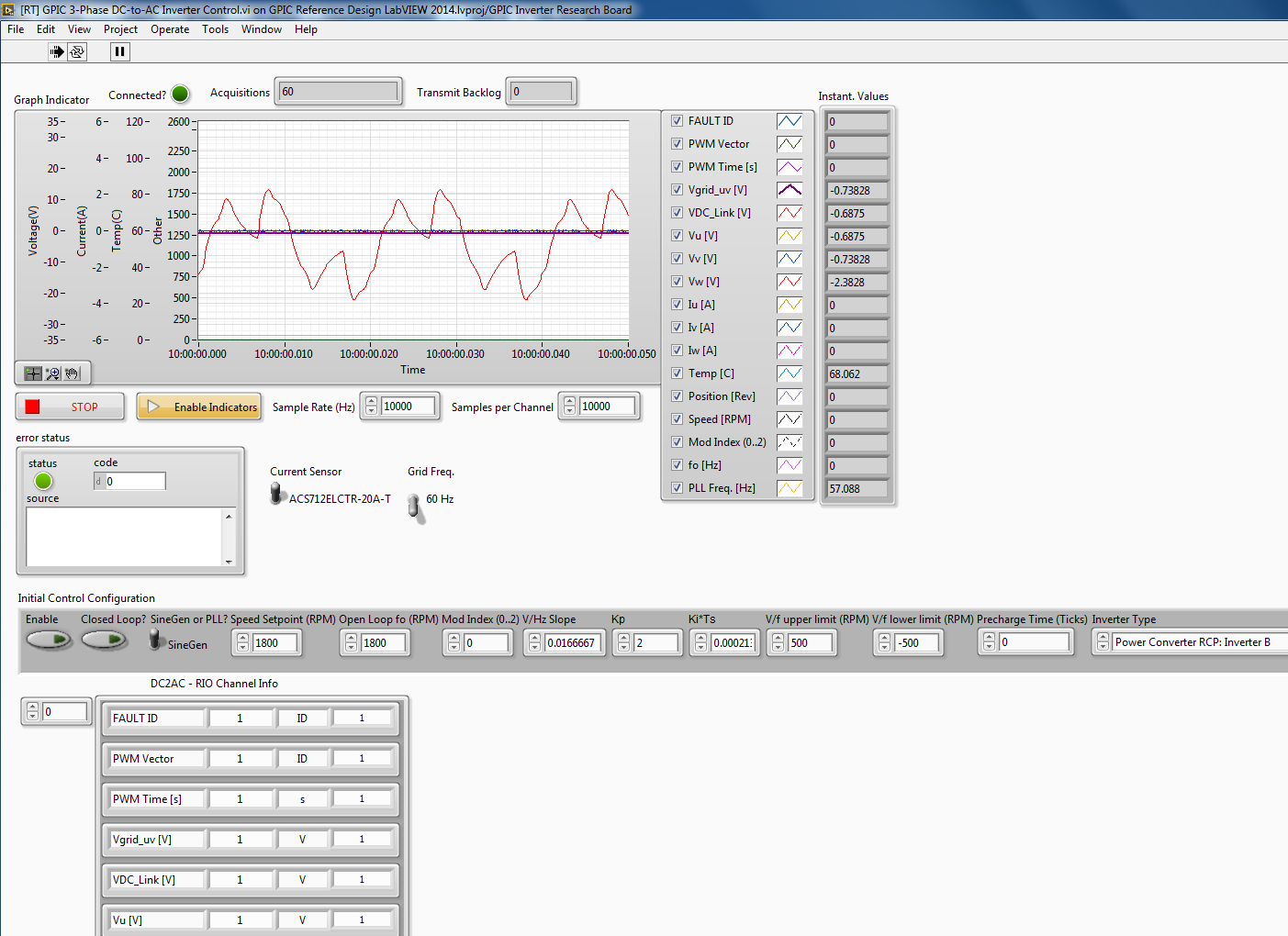
I followed all the steps listed and were pretty sure the research board was correctly linked to the host computer. I will appreciate if you can give me some feedback on how to solve this problem.
Thanks and best regards,
Zihao
10-04-2015 05:17 AM
- Mark as New
- Bookmark
- Subscribe
- Mute
- Subscribe to RSS Feed
- Permalink
- Report to a Moderator
Hi zihao,
By the look of your wave forms, it seems that you havent connected the grid voltage to your GPIC board. You should have a wall transformer of 24VAC that should be first connected to the board in order to start initializing.
I hope that helps.
Ammar
