- Subscribe to RSS Feed
- Mark Topic as New
- Mark Topic as Read
- Float this Topic for Current User
- Bookmark
- Subscribe
- Mute
- Printer Friendly Page
- « Previous
- Next »
NI Power Electronics Control Design V Training Course
11-04-2015 02:47 PM
- Mark as New
- Bookmark
- Subscribe
- Mute
- Subscribe to RSS Feed
- Permalink
- Report to a Moderator
I assume you mean how to make it run in reverse. If not correct me. That would be either doing a negative frequency or subtracting instead of adding in the register where we generate sime waves.
11-04-2015 02:51 PM
- Mark as New
- Bookmark
- Subscribe
- Mute
- Subscribe to RSS Feed
- Permalink
- Report to a Moderator
Yes it meant running in opposite direction.
I said so because with your previous V/f drive, the motor was running in a clockwise direction. If we changed the modulation index below 0, the motor would then run in anti-clockwise direction.
But with the SVPWM module, the modulation index needed to start the motor is atleast 1.1. and reducing the modulation less than 0 has no effect on the direction on the motor and the motor keeps running in anti-clockwise direction.
11-04-2015 03:17 PM
- Mark as New
- Bookmark
- Subscribe
- Mute
- Subscribe to RSS Feed
- Permalink
- Report to a Moderator
well SVPWM does not really have anything to do with direction. It is just PWM based on A, B, and C. You can still use the V/Hz control with the SVPWM as long as it generates A, B, and C. Did you try a negative frequency to see if that changed direction?
11-04-2015 03:19 PM
- Mark as New
- Bookmark
- Subscribe
- Mute
- Subscribe to RSS Feed
- Permalink
- Report to a Moderator
Yes, negative frequency changes the direction of the motor.
11-04-2015 04:37 PM
- Mark as New
- Bookmark
- Subscribe
- Mute
- Subscribe to RSS Feed
- Permalink
- Report to a Moderator
That makes sense. By the way, for an induction machine, the direction of rotation is also determined by the phase sequence (the order in which the motor windings are wired to the inverter half-bridge phases).
11-04-2015 05:03 PM
- Mark as New
- Bookmark
- Subscribe
- Mute
- Subscribe to RSS Feed
- Permalink
- Report to a Moderator
Right, I understand that. I appreciate it.
Brian, I had some technical query reagarding the labview code. As far as i understand SVPWM algorithm implementation for an induction motor, we have differnt modules regarding it. We have, alpha beta transformation, then there is sector determination module, then swtiching time calculation module, symmetric PWM generation module and dead time generation.
I really dont understand why dont you have the alpha beta transformation and swtiching time calculation modules in your labview implementation of SVWPM. The sector determination you have has 4 sectors where as SVPWM is supposed to be implemented with 6 sectors with repect to the 3 phases.
Please enlighten me with the approach.
Thank you
11-04-2015 11:18 PM
- Mark as New
- Bookmark
- Subscribe
- Mute
- Subscribe to RSS Feed
- Permalink
- Report to a Moderator
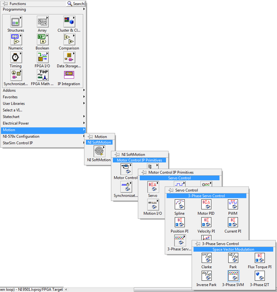
You might also be interested in checking out the Space Vector PWM IP for LabVIEW FPGA that's included with the LabVIEW NI Softmotion Module. After installing, you'll find the Space Vector Modulation core here:
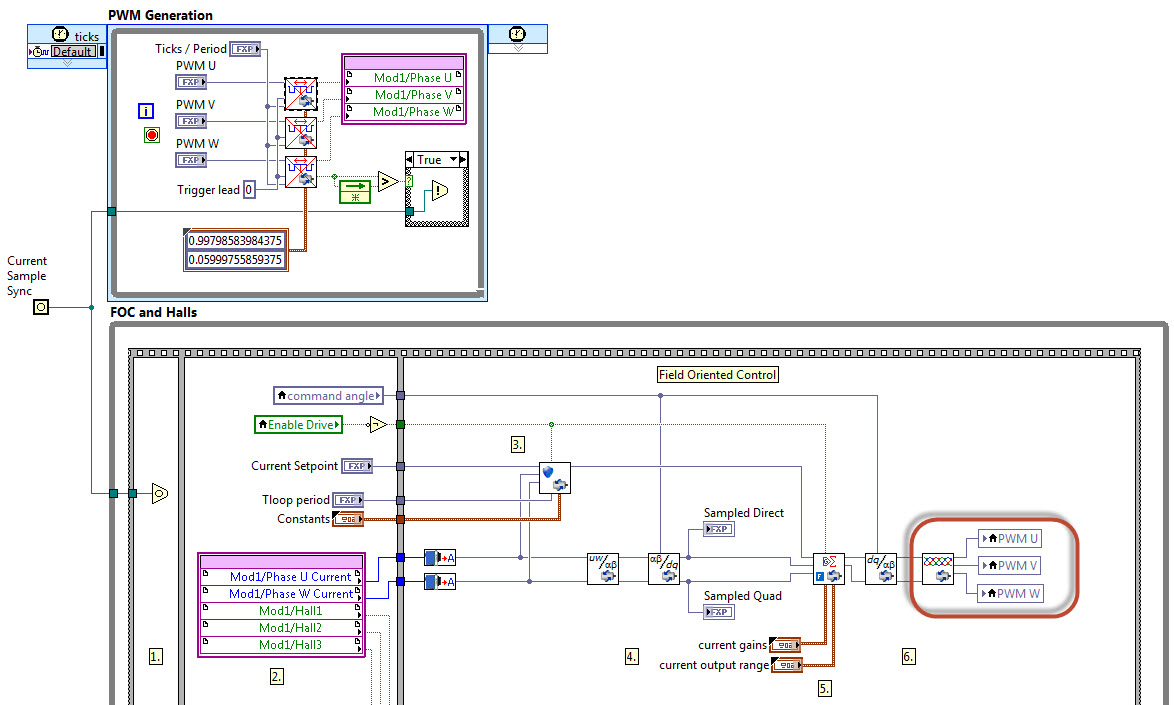
The control outputs are fed to a separate Pulse Width Modulation blocks in a separate Single Cycle Timed Loop as shown below. See the help documentation for details. Note that the toolkit is sold and fully supported by NI and includes commercial quality IP cores. With purchase all of the FPGA IP cores are open and editable.
I've attached a couple of examples for PMSM (brushless DC) field oriented control with space vector modulation in LabVIEW 2014 format. Also, here's a link to download the LabVIEW 2015 NI Softmotion Module.
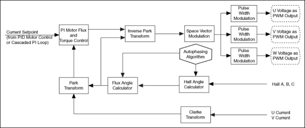
The overall structure for the field oriented control algorithms with SVPWM is shown below.
12-07-2015 09:38 PM
- Mark as New
- Bookmark
- Subscribe
- Mute
- Subscribe to RSS Feed
- Permalink
- Report to a Moderator
Hello Brian,
Your previous share definately helped me in getting into the act and design the SVM.
I had a really quick question if you could help me out or guide me through it. I now want to create a desktop VI in order to read data from the GPIC board and plot it. I understand that i cannot run 2 VIs at the same time so i cannot actually just monitor my ethernet data and get it done.
If you could please just guide me through the process, i will try it out. Or else if you have any VI created that only monitors the voltages and currents and grid voltages and etc, if you could please share that here with me and i will make the necessary changes.
Will appreciate your help in this matter.
Thank you and regards,
Ammar Surti.
03-31-2016 06:14 PM
- Mark as New
- Bookmark
- Subscribe
- Mute
- Subscribe to RSS Feed
- Permalink
- Report to a Moderator
The LabVIEW PID Toolkit is now included with LabVIEW Real-Time/FPGA, so it's not necessary to purchase/install a separate toolkit. Yes, some of the examples in this course use the PID control functions.
- « Previous
- Next »
