- Subscribe to RSS Feed
- Mark Topic as New
- Mark Topic as Read
- Float this Topic for Current User
- Bookmark
- Subscribe
- Mute
- Printer Friendly Page
Question about RMC 9683
10-07-2015 05:06 AM
- Mark as New
- Bookmark
- Subscribe
- Mute
- Subscribe to RSS Feed
- Permalink
- Report to a Moderator
I managed to apparently fry the dual mosfet just before the isolation transformer leading to the Analog Input side (specifically, Q21), therefore all my analog side is now unpowered. Does anyone know what exact model this is so I can replace it?
I attached a picture for clarification.
Any help is appreciated.
- Tags:
- 9683
10-07-2015 08:26 AM
- Mark as New
- Bookmark
- Subscribe
- Mute
- Subscribe to RSS Feed
- Permalink
- Report to a Moderator
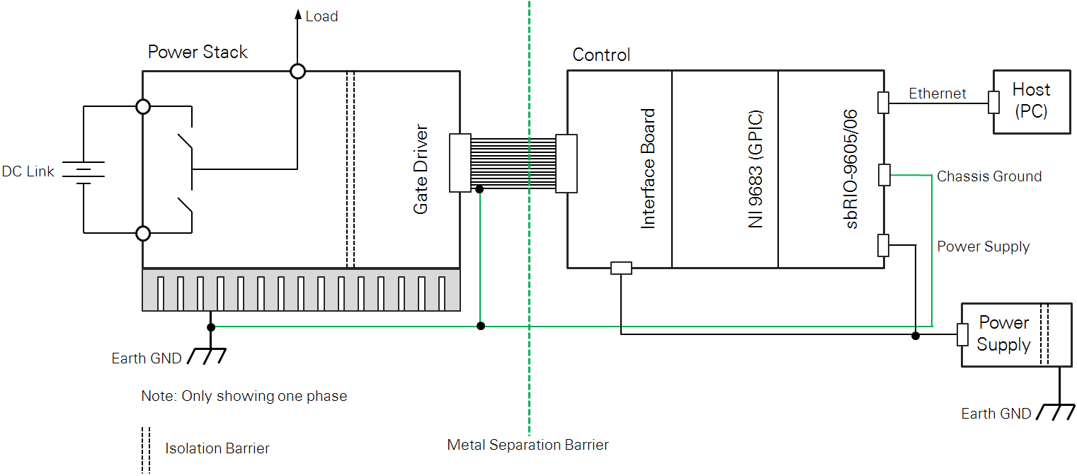
To preserve your warranty, I recommend you return your NI 9683 to NI for repair. To do so, go to ni.com/support and on the right side click on Service Request Manager. Then click on Open a New Service Request, type in NI 9683 as the Product Model Number and under Support Type select Return or repair hardware. However, to answer your question directly, Q21 is Fairchild FDG6303N. To avoid any future problems be sure to review all the information in the NI 9683 User Guide and Specifications, especially the Simultaneous Analog Input connection guidelines (pages 7-9, 15-17) including sensor power supply information, analog input common mode range, overvoltage protection, etc. Also be sure to review the important SYSTEM GROUNDING RECOMMENDATIONS information here and the drawing below.
10-07-2015 08:37 AM
- Mark as New
- Bookmark
- Subscribe
- Mute
- Subscribe to RSS Feed
- Permalink
- Report to a Moderator
Thank you very much for the prompt answer!
To be honest, the way the mosfet was fried was by using the GPIC inside a huge magnetic field - I completely forgot about the isolation amplifier being there, so the core got saturated in the field which then was effectively like a short on the mosfet side. Since I wasn't using the analog inputs before, this was not an issue (everything else works fine) - I only noticed the problem now, when I wanted to use the ADCs for something else.
Also, is there no limitation on the warranty on the card? This is now a 2 year old board, so I thought the warranty expired on it already...
10-07-2015 09:15 AM
- Mark as New
- Bookmark
- Subscribe
- Mute
- Subscribe to RSS Feed
- Permalink
- Report to a Moderator
See here for details on after warranty returns. Basically, if you return for repair after warranty there is a standard repair fee and you get a 90-day warranty included with it.
https://www.ni.com/services/warranty_repair_policies.htm
By the way, I bet people would love to see pictures of the big magnetic field application. In my opinion, it would be cool if we all posted more GPIC application photos on this community site.
10-10-2015 08:32 AM
- Mark as New
- Bookmark
- Subscribe
- Mute
- Subscribe to RSS Feed
- Permalink
- Report to a Moderator
With a correctly designed GPIC interface PCB and proper cabinet cable routing and shielding, examples of the EMC and surge compliance tests commonly passed by sbRIO GPIC converter cabinets are listed below. These compliance tests commonly include ESD, EFT, surge, radiated, ring wave, conducted immunity, etc.
Here are examples of CE Compliance EMC, transient, surge tests passed by the NI sbRIO-9606 Rev. E and NI 9683 GPIC in a 100 kVA 3-phase AC (422-528 VAC, 136 A) and 550-770 VDC, 200 A DC energy storage converter cabinet. Thank you to our customer for allowing me to share these details from their test report:
The system passed all the tests.
The system was measured for pre-compliance with European Standards EN 61000-6-4, "Electromagnetic Compatibility (EMC) – Part 6-4: Generic Standards – Emission Standard for Industrial Environments (2007)," and IEC TS 61000-6-5, "Electromagnetic Compatibility (EMC) – Part 6-5: Generic Standards – Immunity for Power Station and Substation Environments (2001)."
Radiated emission measurement equipment and procedures were in accordance with EN 55011, "Industrial, Scientific and Medical Radio Frequency Equipment – Electromagnetic Disturbance Characteristics – Limits and Methods of Measurement (2010)." The emissions tests described in this report are used for verification with the Code of Federal Regulations Chapter 47, "Part 15 – Radio Frequency Devices, Subpart B: Unintentional Radiators," paragraph 15.107, Conducted Emission Limits and paragraph 15.109, Radiated Emission Limits. Additionally, the tests are used to show compliance with ICES-003, Issue 5 "Information Technology Equipment (ITE) – Limits and Methods of Measurement (2012)."
Immunity measurement equipment and procedures were in accordance with:
• EN 61000-4-2, "Electromagnetic Compatibility (EMC) Part 4-2: Testing and Measurement Techniques – Electrostatic Discharge Immunity Test (2009),"
• EN 61000-4-3, "EMC Part 4-3: Testing and Measurement Techniques – Radiated, Radio-Frequency, Electromagnetic Field Immunity Test (2010),"
• EN 61000-4-4, "EMC Part 4-4: Testing and Measurement Techniques – Electrical Fast Transient/Burst Immunity Test (2012),"
• EN 61000-4-5, "EMC Part 4-5: Testing and Measurement Techniques – Surge Immunity Test (2006),"
• EN 61000-4-6, "EMC Part 4-6: Testing and Measurement Techniques – Immunity to Conducted Disturbances, Induced by Radio-Frequency Fields (2009),"
• IEC 61000-4-12, "EMC Part 4-12: Testing and Measurement Techniques – Ring Wave Immunity Test (2006)."
Per the EMC test plan: For emissions, the system is Class A, Group 1 equipment. Immunity requirements and performance criteria are from EN 61000-6-5, Table 1, "Immunity Specifications – Enclosure Ports," Table 3, "Immunity Specifications – Low-voltage AC Input Power Ports and Low voltage AC Output Power Ports," and Table 4, "Immunity Specifications – Low-voltage DC Input Power Ports and Low-voltage DC Output Power Ports." There are DC input lines and AC output/control/transformer lines. There are not any possible magnetically sensitive components.
The system is compliant with the EN 61000-6-4 radiated and conducted emissions limits. The system complies when subjected to EN 61000-6-5 levels for ESD, EFT, surge, radiated, ring wave, and conducted immunity.
Section X compares the unit radiated emissions to the applicable limit from 30 MHz to 1000 MHz in accordance with equations identified in VI and the output identified in measurement procedure VIII-1. Section XI compares the unit conducted emissions to the applicable limits from 150 kHz to 30 MHz in accordance with measurement procedure VIII-2. Sections XII through XVII reference measurement procedures of VIII-3 through -8 in accordance with susceptibility and performance criteria described in Section V for type acceptance and per the manufacturer's test plan.
1. 4-kV electrical fast transients, delivered in 5-kHz bursts to the DC power lines
2. 2-kV electrical fast transients, delivered in 5-kHz bursts to the AC lines
3. 2-kV line-to-line/4-kV line-to-ground, 1.2/50microsecond combination wave surges, delivered directly or by phase synchronization to the DC input
4. 2-kV line-to-line/4-kV line-to-ground, 1.2/50microsecond combination wave surges, delivered directly or by phase synchronization to the AC lines
5. 1-kV line-to-line/2.5-kV line-to-ground, 1 MHz ring wave wave surges, delivered directly or by phase synchronization to the DC input
6. 0.5-kV line-to-line/1-kV line-to-ground, 1.2/50microsecond combination wave surges, delivered directly or by phase synchronization to the AC lines
