- Subscribe to RSS Feed
- Mark Topic as New
- Mark Topic as Read
- Float this Topic for Current User
- Bookmark
- Subscribe
- Mute
- Printer Friendly Page
StarSim Aplication Example: Transmission Line Distrance Protection
10-05-2012 08:42 AM
- Mark as New
- Bookmark
- Subscribe
- Mute
- Subscribe to RSS Feed
- Permalink
- Report to a Moderator
Distance protection is a kind of transmission line fault clearance technique; it is based on the impedance measurement. The impedance measurement algorithm needs to meet two rules.
1. The result should be proportional to the distance between the fault point and the relay installation point.
2. The result should not be related with the fault type.
In order to meet the above requirements, these formulas are used to calculate the impedance.
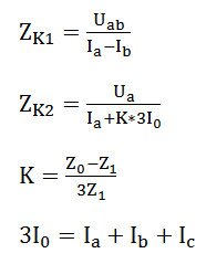
where Z0 is the zero sequence impedance, Z1 is the positive sequence impedance, I0 is the zero sequence current. Zk1 is for the phase to phase faults, Zk2 is for the phase to ground faults. The above formulas are for phase A. The formulas for phase B and phase C are similar.
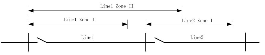
For the distance relay, the whole protection distance will be divided into several zones. Zone 1 covers 80%-90% of the line which this relay protects. If the fault happens in the zone I, this relay will trip the line without any delay. If the fault happens in the zone II, the trip command will be delayed for a while in order not to compete with the Zone I protection command of next line.
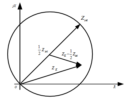
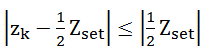
The distance protection relay usually uses the directional relay circle to judge whether the fault happens in its area.
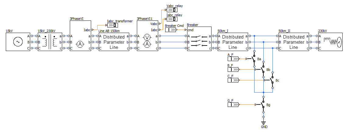
Distance Protection Demo
This system consists of two long distance transmission lines. The length of first line is 150km, the length of second line is 100km. There are four breakers at the middle of the second line. These breakers are used to generate different kinds of faults. The second line is equipped with a distance protection relay. This relay will trip the line when it detects the fault. Since the fault point is at the middle of the line, this demo is mainly used to verify the zone I protection of this relay.
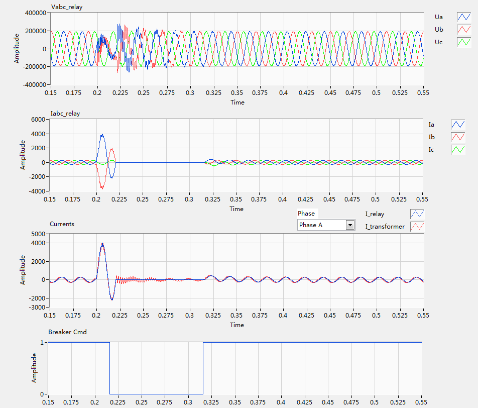
The phase A to phase B fault is simulated here. The fault happens at 0.2s. The distance protection relay detects the fault and send the trip command around 0.216s. The relay re-closes line around 0.316s. The first two waveforms show the voltage and current of relay installation point.
The third waveform control compares the currents of two ends of first transmission lines. It can be observed that the currents of two ends of a long distance transmission line will be quite different. If the simple RL model is used for the transmission line modeling, the currents of two ends will be the same. This is that reason that the special modeling technique (the distributed line model) is necessary for accurately describing the long distance line.
The fourth waveform records the relay trip command, 1 for the close command, 0 for the open (trip) command.
Kevin Wang | kevin.wang@modeling-tech.com
R&D Director
ModelingTech Energy Technology Company
