- Document History
- Subscribe to RSS Feed
- Mark as New
- Mark as Read
- Bookmark
- Subscribe
- Printer Friendly Page
- Report to a Moderator
- Subscribe to RSS Feed
- Mark as New
- Mark as Read
- Bookmark
- Subscribe
- Printer Friendly Page
- Report to a Moderator
Contact Information
University: Iowa State University
Team Members (with year of graduation):
Software/Electrical: Nathan Beougher (2013), John Heinig (2017), Chris Walck (2013)
Mechanical/Other: Ricardo Canahui (2014), Joseph Gettemy (2017), Katie Goebel (2014), Alex Grant (2016), Aren Hill (2013), Diana Jarrell (2014), Brian Jend (2014), Kurt Lundeen (2013), Ryan McCleish (2012, 2015 Grad), Quinn Murphy (2016), David Peiffer (2015), Lauren Wickham-Kolstad (2014), Kyle White (2013), Andrew M Klein (2014), Ashley Pitkin (2013), Brandon Koepke (2015)
Faculty Advisers: Jim Heise
Email Address: ngbeough@iastate.edu, jheise@iastate.edu
Submission Language: English
Project Information
Title
Iowa State University's Winning Lunabot at NASA's Lunabotics Mining Competition 2013
Description
Iowa State University's Team LunaCY designed and built a robot (aka lunabot) to autonomously mine, transport, and deposit regolith (surface material found on the moon and Mars) in NASA's Lunabotics Mining Competition 2013.
Products
LabVIEW 2012 (FPGA, Robotics, Real-Time), Single-Board RIO 9632, NI LabVIEW Robotics Starter Kit (DaNI)
Custom breakout PCB for the sbRIO (1), DC-DC Converter (1), Custom DC-DC Converter PCB (1), Castle Creations Mamba Max Pro ESC (2), Castle Creations Mamba Monster ESC (2), Castle Creations BEC Pro (2: 5V, 12V), US Digital S4 Miniature Optical Shaft Encoder (2), US Digital MA3 Miniature Absolute Magnetic Shaft Encoder (1), L3G4200D Gyroscope (1), D-Link DAP-1522 (1), Reed Switch (2), Arcade Button (2), Vex Pro Mini CIM Motor (3), Vex Pro BAG Motor (2), Vex Pro VersaPlanetary Gearbox (4), Linear Actuator (1), Laptop (1), Joystick (1), D-Link Wireless Router (1), D-Link Wireless Bridge, Keyence Digital Laser Sensor
The Challenge
In NASA's Lunabotics Mining Competition, teams must design and build an autonomous or teleoperated lunar mining robot capable of collecting, transporting, and depositing lunar regolith simulant. The robots must also be capable of safely traversing an obstacle zone consisting of rocks and craters to get to and from the mining zone. A large emphasis was placed on both weight and autonomous operation for this year's competition.
The Solution
This year's lunabot was designed based on our winning lunabot from last year's Lunabotics Mining Competition. The locomotion of the lunabot is provided by a custom designed track and frame system. It was designed to be a very stable platform with maximum ground clearance allowing it to safely go over the obstacles as well as traverse through craters in the competition arena. The tracks were controlled with a closed-loop PID control system implemented in the FPGA with feedback from quadrature encoders. Mining of regolith was performed by a combination hopper and digging conveyor system. The hopper and digging conveyor system was mounted on an upper frame which pivoted about a single hinge point. A single linear actuator was used to move the hopper/conveyor system and was also close-loop controlled using an absolute magnetic position encoder at the hinge point also implemented in FPGA. Having both systems combined into a single structure allowed us to minimize the number of actuators required by the entire system. Therefore, both the mining depth of the digging conveyor and the hopper dump position were controlled by this single actuator. The digging conveyor, itself, was open-loop controlled but we had plans to use the current draw of the conveyor motors to control the foward speed of the lunabot during mining.
Autonomy was a huge emphasis for this year's competition so we looked into several different options to achieve this goal. One major sensor that we had looked into was a SICK laser range finder. Unfortunately, we were unable to get this to work in the short time that we had to implement it. So, we decided to go with a simple approach to autonomy. The state diagram below shows the our autonomy implementation. The following figure shows the ideal paths in the arena.
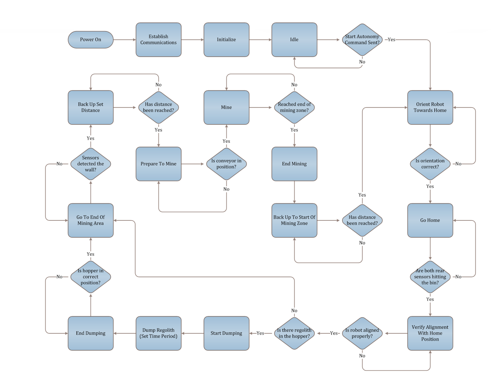
Autonomy State Diagram. This is the states of the state machine that was used for the competition.
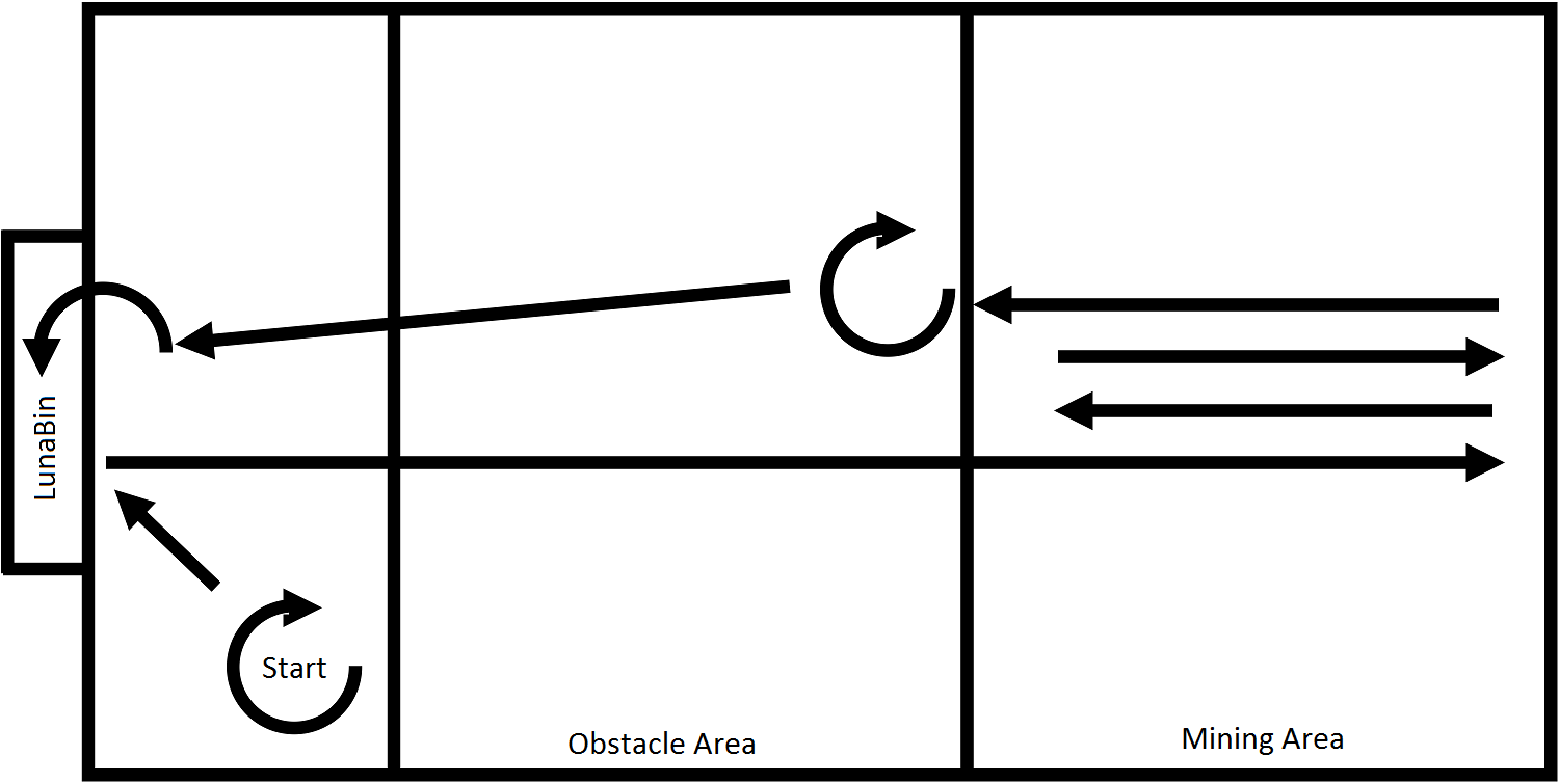
Ideal authomy paths.
Benefits of LabVIEW and National Instruments' hardware:
The single-board RIO offers a compact and well integrated package for real time processing, FPGA, and programmable inputs and outputs. This allowed us to take advantage the benefits of both an FPGA and real time processor with no time lost in integrating the two systems.
The control software for our lunabot was developed in parallel with the actual robot, which left only a short period of time for integration and testing at the end of the project. The use of the robotics starter kit proved to be an ideal test platform for our robot, and was responsible for a relatively painless integration of the control software with the final robot.
Without the LabVIEW FPGA module, it would have been impossible to use an FPGA to develop the low level controls within the time constraints of the project. The high degree of reliability the FPGA provides is important when it comes down to the reliability and safety of the systems, especially when this robot will be used for our STEM outreach events.
Images and Video
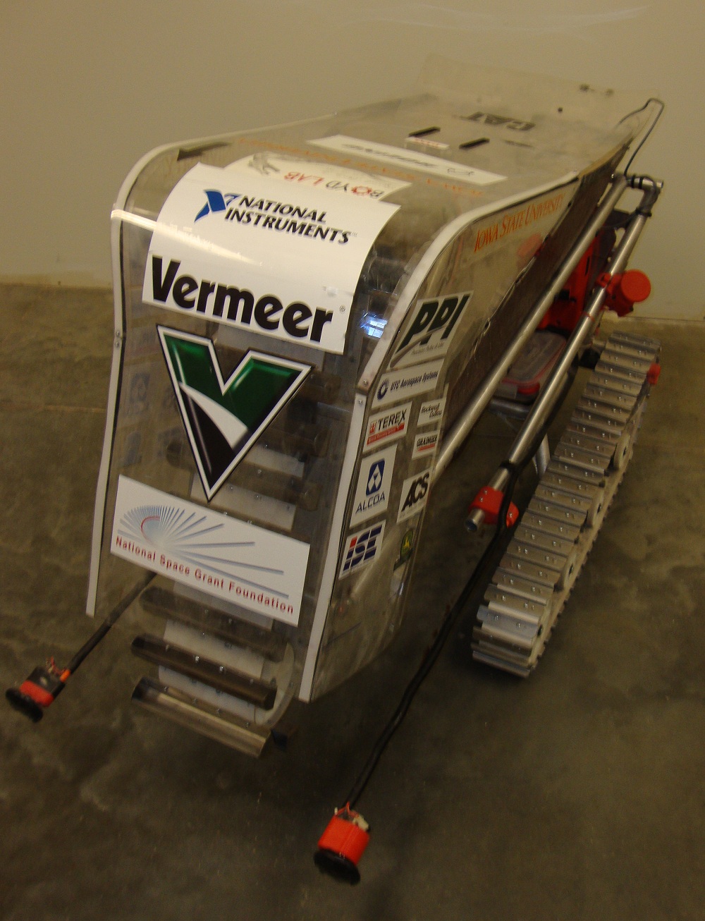
Front View: This is a front view of the lunabot showing conveyor system shrouded by the dust sheilds as well as the front tactile sensors.
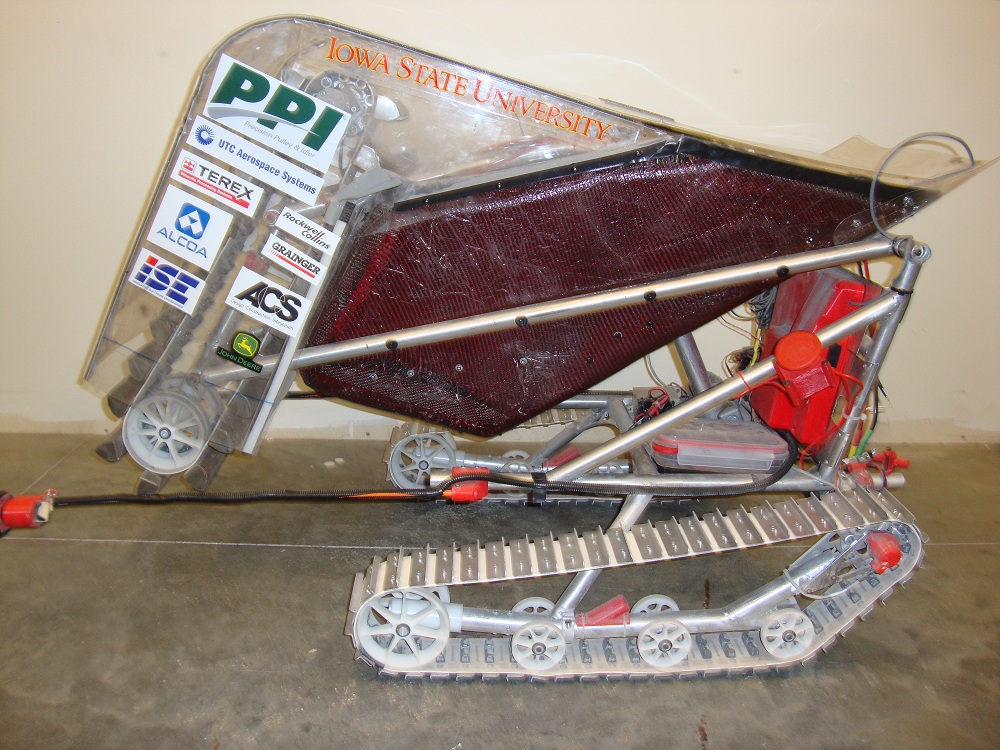
Side View: This is the side view of the lunabot showing all of the major systems.
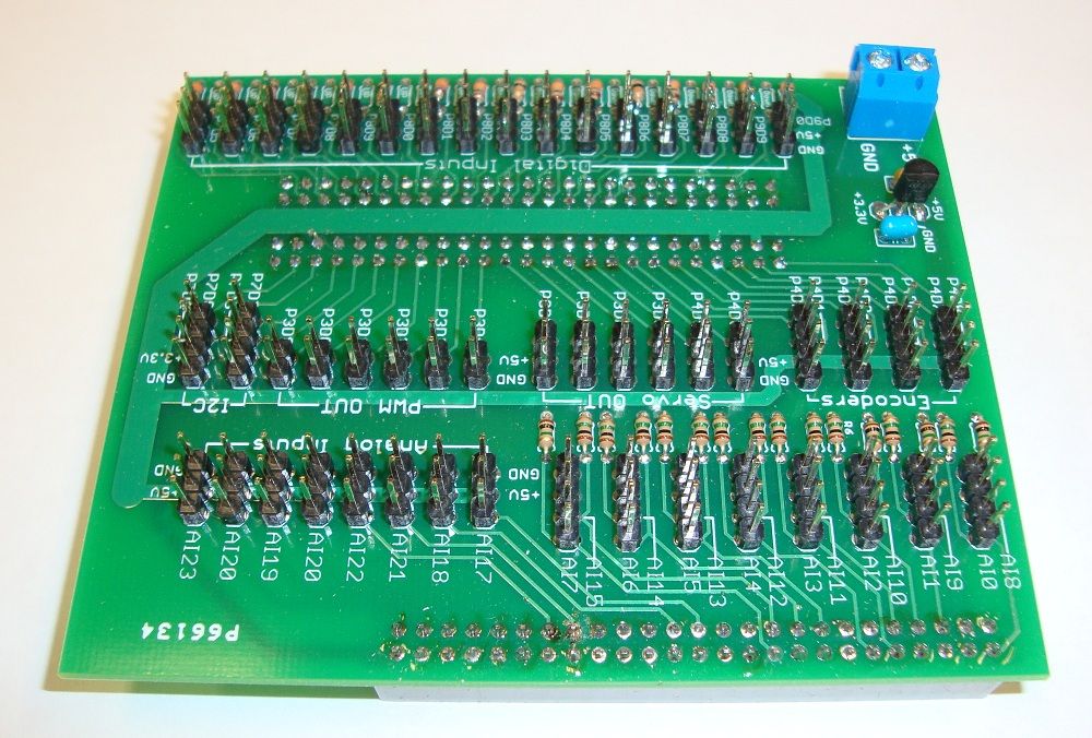
Custom Single-Board RIO Breakout Board: Custom designed PCB to breakout both digital and analog pins for various inputs and outputs including PWM outputs, I2C Communication, Quadrature encoder inputs, and digital and analog inputs. This board mounts directly onto the sbRIO.
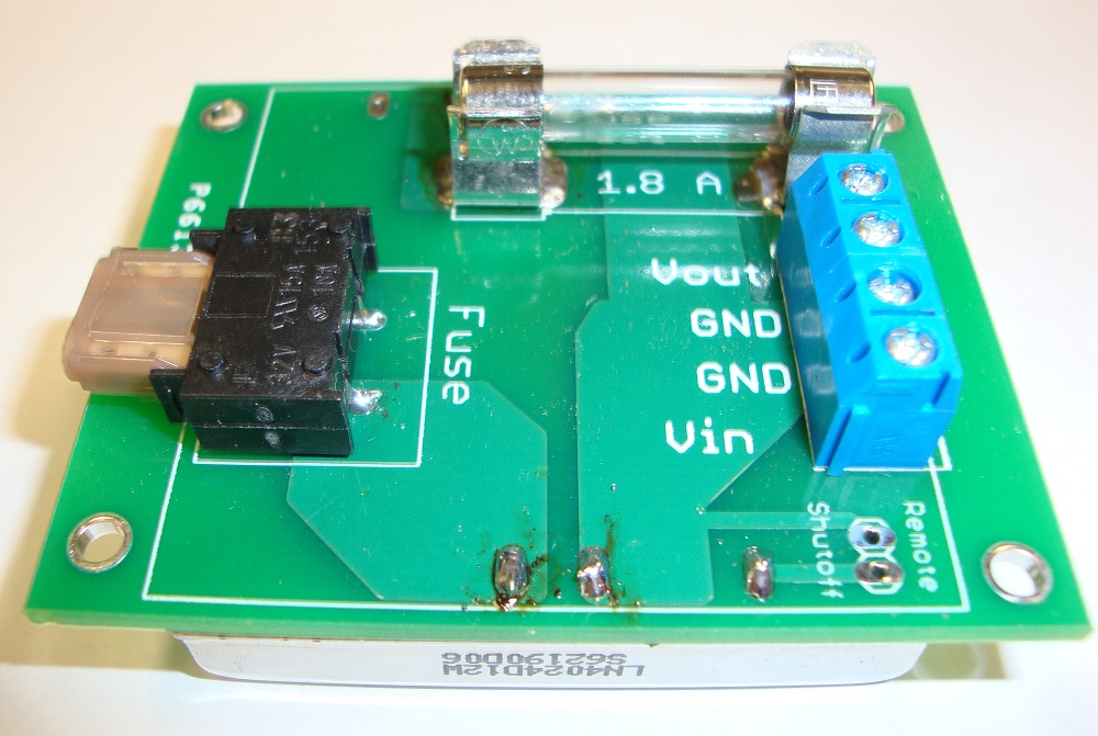
Custom Power Supply PCB: Custom designed PCB for a DC-DC Converter to power the sbRIO (The DC-DC Converter is on the bottom).
Video: Our second competition run. It autonomously found home, traversed the arena, and mined 31.5 kg of lunar regolith simulant. After mining, it was unable to find home again at which point we had to override with manual control (at about 2:15). We ended the run with 115 kg. This run secured first place for the on-site mining award.
Our robot was fully functional in manual mode. The autonomy algorithm was mostly implemented and tested but did not perform as expected in competition due to an unforeseen failure mode as seen in the above video.
The mechanical design began at the begining of the school year (August 2012) and the software developement began approximately in February 2013. The robot was operational by the time the competition started on May 20th, 2013.
There are several things that could be changed to impove the project overall. One major mechanical change is to better mount (possibly dynamically) the single beam laser used to locate our target. For software, one major improvement would be to optimize (i.e. minimize) the data transmission from mission control to the robot especially during autonomous operation.
Thanks to our sponsors:
ACS
Alcoa
Boeing
Caterpillar
Grainger
Innovative Software Engineering
John Deere
National Space Grant Foundation
National Instruments
PPI
Rockwell Collins
TEREX
UTC Aerospace Systems
Vermeer
Also, Thanks to the other club members who contributed to other aspects of the Lunabotics Mining Competition.
- Mark as Read
- Mark as New
- Bookmark
- Permalink
- Report to a Moderator
Hi nice work.
Just wondering what was your localisation system to get heading and position?
- Mark as Read
- Mark as New
- Bookmark
- Permalink
- Report to a Moderator
What we did was use a beam-break laser sensor to determine when the rear of the robot was pointed at the collection bin target (which was retroreflective). Then we backed up and aligned with the wall using two tactile sensors which controlled the tracks such that we end up perpindicular to that wall. Now that we know our location and heading, we sort of dead reckoning from there.
- Mark as Read
- Mark as New
- Bookmark
- Permalink
- Report to a Moderator
Hi, great job last year! What kind of resistors did you use for the digital inputs?
- Mark as Read
- Mark as New
- Bookmark
- Permalink
- Report to a Moderator
What method did you use for converting 5v to 3.3v for the I2C components?
- Mark as Read
- Mark as New
- Bookmark
- Permalink
- Report to a Moderator
We never needed to translate the I2C logic levels because 1) the sbRIO-9632 is 5V tolerant and 2) the I2C IMU was powered by 3.3V.
