- Document History
- Subscribe to RSS Feed
- Mark as New
- Mark as Read
- Bookmark
- Subscribe
- Printer Friendly Page
- Report to a Moderator
- Subscribe to RSS Feed
- Mark as New
- Mark as Read
- Bookmark
- Subscribe
- Printer Friendly Page
- Report to a Moderator
Hello Developers,
I have recently been working on a project with the NI myDAQ to improve students' understanding of Bioelectrical principles. The project is called myBIA and aims to showcase how an electrical signal travels through the different tissues of the human body.
Bioelectrical Impedance Analysis involves sending a very small current through two points on the body — approximately 800 mA at 50 kHz (This stimulus is unable to be felt by the patient.) It is then possible to measure the resulting potential difference between these points and calculate resistance using Kirchoff's Laws. The underlying theory in this procedure is based on the subject's physical characteristics and his/her resistance to a current. Lean tissue offers less resistance to a current as it is composed of more water and electrolytes than adipose tissue. A distinct advantage, unlike with other body composition measurements, is that to perform a BIA test no special training or operator skill is required. While the accuracy of BIA is reported to be similar to skinfold measurements, research is continuing in order to improve the accuracy of the governing equations. Overall this procedure has great merit for making relatively accurate measurements both easily and quickly.
The main application areas consist of use by health professionals, athletes and domestic where the mesurement can be combined with traditional weighing scales.
Youtube Video
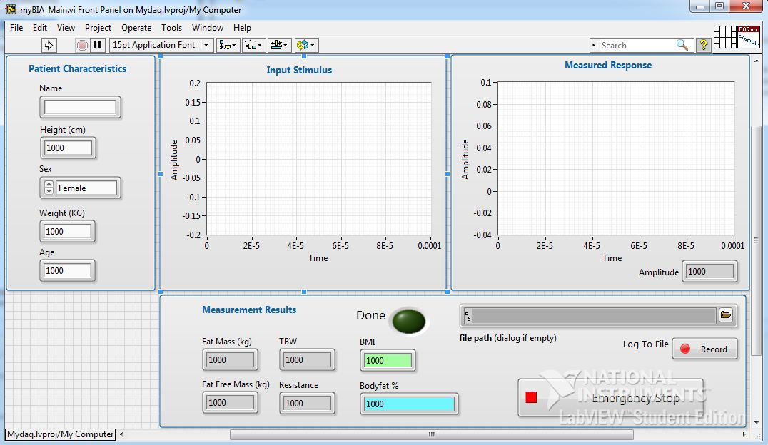
Front Panel
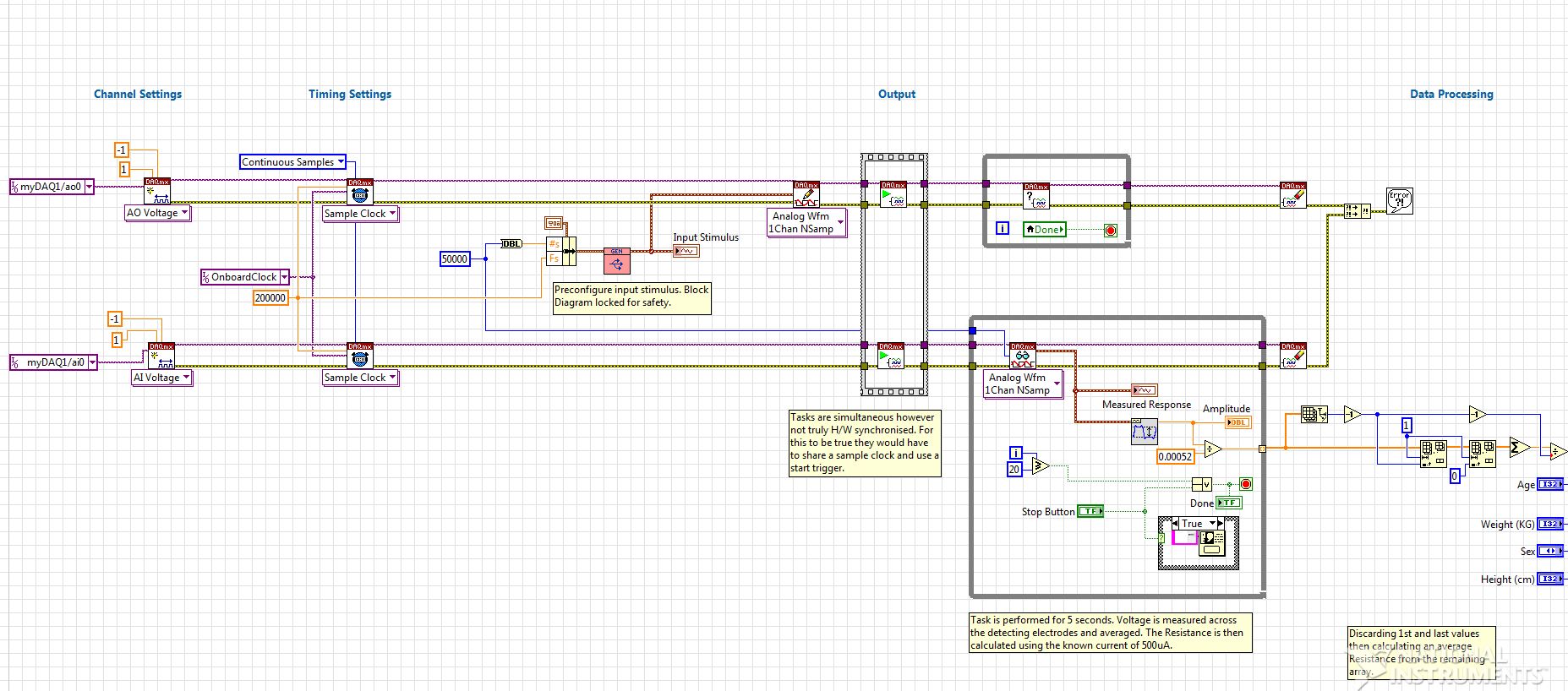
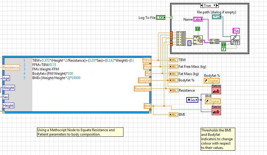
Block Diagram
For more information please see myBIA.zip and the enclosed Student Guide in the downloads section below.
Thanks for watching!
Please Note: This project involves stimulating the human body with electrical signals and is undertaken completely at your own risk. For safety reasons I would recommend National Instruments devices which provide electrical isolation and are certified for medical use. The NI myDAQ is not.
Applications Engineer
National Instruments
- Mark as Read
- Mark as New
- Bookmark
- Permalink
- Report to a Moderator
Hi Jamie,
I would like to know that in which range of the load I have to count when I want to create the current source on the BIA? I am asking because when I want to create some current source on 800uA I have to know load. And it is quite hard when I create the current source on the load 2kohm and the load of the human body would be bigger the current would not be 800uA, but for example 620uA and then I cannot calculate the resistance correctly.
Thank you very much for your respond and of course for your help
Best regards
Majjo
- Mark as Read
- Mark as New
- Bookmark
- Permalink
- Report to a Moderator
Hi Majjo,
I'm afraid I don't fully understand your question. Have you downloaded the .zip file and looked at the documentation?
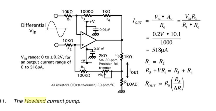
The Howland Current Pump circuit is used to provide the constant current source and much information can be found on this either online or in engineering textbooks.
Let me know how you get on.
Applications Engineer
National Instruments
- Mark as Read
- Mark as New
- Bookmark
- Permalink
- Report to a Moderator
Hi Jamie,
I tried to perform the experiment with Howland current source circuit you showed.
Then I couldn't get the current level around 520uA.
It looks like the circuit has some frequency dependent characteristics so the level of current seemingly goes down beyond 1kHz.
On top of that, myDAQ board doesn't have goog shape of sine wave at around 50kHz.
Recapitulating my experiment, my circuit looks making around 10~20uA(peak-peak).
Could you comment on my work?
What do you think about my following assumption?
Vi=0.1V, by calculation, I(load)=0.1mA(Because R13=1k and I(load)=roughly Vi/R13)
Then if the ouput level at 50kHz decreases by 1/10 compared to the level of 1kHz, it should be 0.01mA(10uA)
As a matter of fact, I just started to learn Labview recently, so please understand my probable wrong-assumption and so on.
Thanks
- Mark as Read
- Mark as New
- Bookmark
- Permalink
- Report to a Moderator
Hi Harry,
Howland circuits have long been widely used as an accurate source for exciting tissue over a wide frequency range. Unfortunately, the operational amplifier limitations and resistor tolerances can cause undesired behaviors if not chosen very precisely and carefully. Would you be able to message me your component list and perhaps I can offer some further advice? Additionally, do you have access to anyone with further expertise in analogue/medical electronics who may be able to take a look at your circuit? Forgive me if you are yourself experienced in this area.
Regarding your assumption, the following is the particular circuit implementation and equations which worked for me. Is this also what you are following?
I look forward to hearing from you.
Jamie
Applications Engineer
National Instruments
- Mark as Read
- Mark as New
- Bookmark
- Permalink
- Report to a Moderator
Hi Jamie,
It is really exciting for me to communicate with you like this.
When I build my circuit, I just followed your explanations shown with pictures and each steps in your student guide.
Here is the circuit diagram.
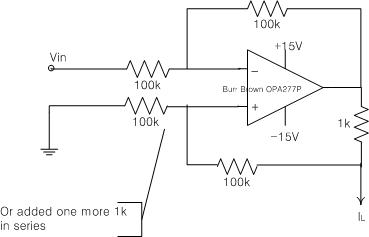
By the way, shouldn't the calculation of 0.2V*10.1/1000 be 0.00202(2.02mA) on your above explanation?
Regards,
Harry
- Mark as Read
- Mark as New
- Bookmark
- Permalink
- Report to a Moderator
Sir,
Can you please tell me the specifications of the protoboard used in this research of yours? Can I try using the protoboard kit developed by Elenco.I am sending you the link of the protoboard(http://sine.ni.com/nips/cds/view/p/lang/en/nid/210925).
Another thing, I wanted to ask is whether any simulator is required as we are giving the patient alternating current of frequency 50 KHz(means will it not affect the individual)?Means just by simply attaching surface electrodes like the disposable foam pad electrode, is it possible to send 800 mA and 50 KHz signal?
- Mark as Read
- Mark as New
- Bookmark
- Permalink
- Report to a Moderator
Hi Arkaprabha,
In my case, I utilized NI myDAQ and a general purpose bread board.
And in regard to 800mA, it is the output signal from the circuit which applies to human skin.
Thanks,
Harry
- Mark as Read
- Mark as New
- Bookmark
- Permalink
- Report to a Moderator
Thanks for your reply Mr.Harry.
Actually I wanted to confirm i as human heart cannot resist beyond 30 mA of current and that too here we are supplying ac current. How is this possible?
One more thing have you used any signal stimulator or any sort of such thing for giving current to the skin?
- Mark as Read
- Mark as New
- Bookmark
- Permalink
- Report to a Moderator
I am using a general purpose breadboard and a Compact-DAQ for myBIA . My question is that in order to design the 800mA and 50 KHz current circuit, to be given as an input stimulus to the human body, I will be using a function generator for producing a 50 KHz signal , but I am not getting any idea to design the 800 mA circuit.
Being from a remote area, I donot have access to OPA277P Op-amp, so I want to use IC 741. Also, I have followed all the discussions on your profile regarding this and the material you have uploaded, but I am unable to understand the same( Howland circuit pump).
Kindly suggest me a simpler way.
- Mark as Read
- Mark as New
- Bookmark
- Permalink
- Report to a Moderator
Hi Jamie,
Happy New Year to you.
I followed your circuit implematation as well as mine.
And I used resistors manufactured by TE Connectivity(TYCO) marked as "H8100KBYA" or WEI WYN marked as "RC55Y 100K 0.1%" for 100k.
Those look like metal film resistors and 1/4W rating.
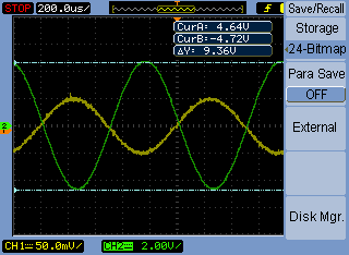
When I set input voltage coming from myDAQ as 0.1Vpp(1kHz), the oscilloscope displays (Rload=100k) as follow.
Vpp_input varies 106~119mV in reality.
(In my circuit, I calcluated the load voltage as 100k*(0.1V/1k) = 10V)
By the way, when the output voltage goes over around 27Vpp, the waveform starts to be clipped.
FYI, my email address is habumm@naver.com.
- Mark as Read
- Mark as New
- Bookmark
- Permalink
- Report to a Moderator
Hi Mate thanks for the help,but for some reason i cant open the main file on labview since there is no location,can you send it by email please?only two weeks left to design it.It will be grateful from you
Thank you a lot
email:seanyal@hotmail.fr
