- Document History
- Subscribe to RSS Feed
- Mark as New
- Mark as Read
- Bookmark
- Subscribe
- Printer Friendly Page
- Report to a Moderator
- Subscribe to RSS Feed
- Mark as New
- Mark as Read
- Bookmark
- Subscribe
- Printer Friendly Page
- Report to a Moderator
NI myRIO-1900 for Industrial Servo Drive Control
Introduction
The National Instruments myRIO-1900 is a portable reconfigurable I/O (RIO) device that students can use to design control, robotics, and mechatronics systems. It has 10 analog input (AI) channels, 6 analog output (AO) channels, 40 digital input/output (DI/O) lines and UART-TX/RX lines. Some DI/O lines also carry secondary functions such as encoder, SPI, PWM and I2C.
Though myRIO-1900 is designed for academic purpose, it can also be used for industrial devices control due to its standard hardware design and various interfaces. The advantages and disadvantages of myRIO for industrial devices control will be discussed in this document. As the wide usage of servo drives in industry, myRIO-1900 for servo drive control is taken as the example.
Generally a servo drive includes a servo unit and a servo motor. The servo unit receives commands from host controller and works in velocity control mode, position control mode or torque control mode. The servo unit may communicate with its host controller via serial port or parallel ports. NI myRIO-1900 can provide corresponding interfaces for both data communication modes directly or indirectly when acted as the host controller of the servo drive.
Electrical Connection
Serial Port Communication
Most of the servo drives have a connector for serial port communication. NI myRIO-1900 has UART-TX/RX lines so that it can be used to control servo drives by serial port communication. Generally the servo drive’s serial port connector needs input or output signals which conform to RS-232 electrical level standard. But myRIO-1900 UART lines input or output signals using TTL electrical level standard. The polarity definition of the two kinds of electrical level is contrary. In this case, there should be a level conversion unit when myRIO is selected as the controller for servo drives which work in serial communication mode.
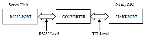
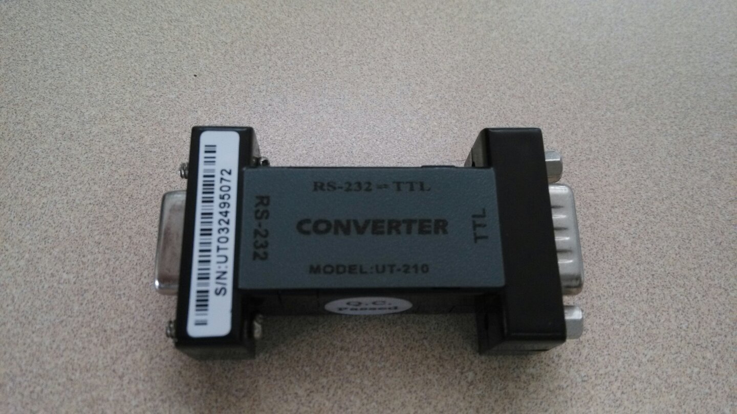
The picture above is an actual converter for conversion between TTL electrical level and RS232 electrical level.
The advantage of serial port control is its simple connection. It just needs a data cable(or with a converter) that fits connectors of both controller and servo drives. But it costs more time for data transmission which leads to response delay of both sides.
Parallel Ports Communication
Parallel ports control is more efficient for servo drive control. It needs less time for data communication between servo drive and its controller. But the electrical connection is more complicated. For the servo drive, each type of input or output signal may needs corresponding input or output circuit. When acted as the host controller, myRIO-1900 can be directly connected to parallel ports of servo drives with its corresponding interfaces in most of situations. But extra circuits are still required in some cases.
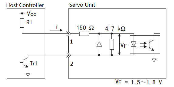
1. Analog Input Circuit
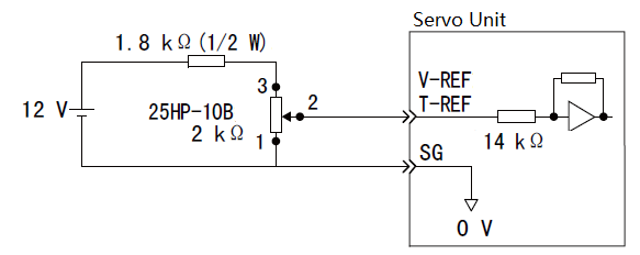
The myRIO has 4 AO channels which range between 0V and 5V on A/B-Port and 2 AO channels which range between -10V and 10V on C-Port . So if required highest analog input is within the AO range, myRIO can be connected to the corresponding parallel port of the servo drive directly. In the above case, user can directly connect available myRIO AO channel to V-REF/T-REF port of servo unit and AGND channel to SG port without extra circuit. But a booster circuit should be added between myRIO and the servo drive when the required input is beyond the output range of myRIO AO channel.
2. Pulse Signal or Level Signal Input circuit
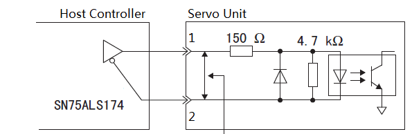
Generally in the above two cases, the available DI/O channels or the PWM channels (sharing the same pin with some DI/O channels ) on myRIO can be directly connected to parallel port 1 of the servo drive and digital ground (DGND) channel to parallel port 2.
3. Sequential Control Input Circuit
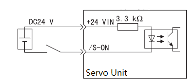
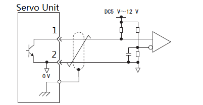
In this case, myRIO is connected to the servo drive with a relay and used for controlling on-off action of the relay . A DO or an AO channel with the GND port of myRIO is connected to control ports of the relay and the switch ports of the relay connected to DC GND and /S-ON port of servo unit. Be careful with the threshold for the action of the relay so that the DO or AO output voltage can control the relay as expected. Due to the limited power output voltage (+5V, +/-10V, +/-15V), extra DC source is required when necessary.

In this case, extra circuit is required and myRIO DO or AO channel can be used for transistor on-off control so the input circuit can satisfy the input requirements for the servo unit. Be careful with polarity definition.
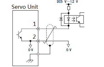
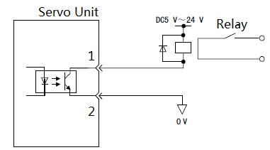
4. Open-collector Output Circuit
In above cases, the servo unit may need several kinds of output circuits for connection with its controller. In fact, myRIO can be directly connected to the output port of such type without extra output circuits. If so, DI port of myRIO is connected with parallel port 1 of the servo unit and DGND port connected with parallel port 2.
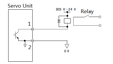
5. Photoelectric Coupler Output Circuit![]()
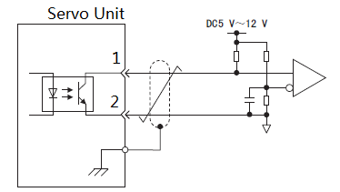
In above cases, the DI port on myRIO can be directly connected to parallel port 1 of the servo unit and DGND port connected with parallel port 2.
6. Linear Drive Output Circuit![]()
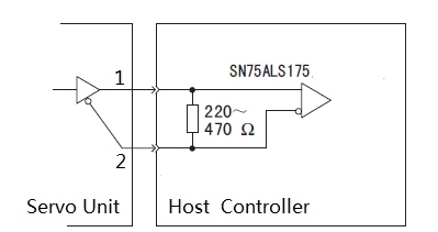
In this case, myRIO can also be directly connected to the servo drive. Just connect parallel port 1 with DI channel of myRIO and parallel port 2 with DGND of myRIO. Usually the servo drive will output the encoder information from this type of port. NI myRIO has corresponding encoder pin for receiving such data signals.
Software Control
The various interfaces on board is not the only advantage for myRIO being the host controller of servo drives or other industrial devices. Another advantage comes from its powerful develop tool--LabVIEW myRIO. With the help of LabVIEW myRIO, any user can have easy access to any interface on myRIO board by a simple Express VI. There are also many useful modules for designing users’ desired control algorithms. After codes completed, LabVIEW myRIO can help deploy codes into processor and FPGA of myRIO.
NI myRIO-1900 covers the most basic interfaces, but it also has some deficiencies. The range of AI, AO and DIO channel is limited that sometimes it’s not enough to control the industrial devices.
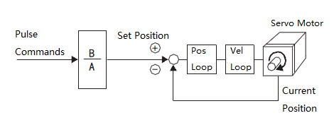
The above figure shows the working principle of position control. Position control is one of the main control modes for servo drive control. When working in position control mode, the servo unit receives a certain number of pulses as command signal from controller and drives the motor to certain position. There should exist a formula between the angle of rotation of the motor and the number of received pulses. Users can use the PWM function of myRIO for pulse commands generation. The PWM Express VI in LabVIEW myRIO can help users set the duty cycle and frequency of PWM. By setting different frequency, user can control the velocity of the servo motor when the servo unit works in position control mode. The frequency of PWM that myRIO can generate is discrete while 40HZ being the minimum frequency. But due to the on-off time delay of PWM, it’s difficult for myRIO to generate precise amount of pulses during specified time via its PWM function. So if myRIO is used for precise position control of the servo motor, close-loop feedback control should be used.
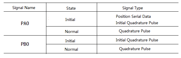
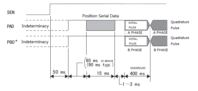
The encoder on myRIO can receive two types of signal: quadrature phase signal and step signal with direction. Generally the servo unit may transmit the data of servo motor encoder by quadrature phase signal via specific port. There’s no problem for encoder on myRIO analyzing the motor data if the specific port of servo unit always transmits the same type signal. But some servo drives may not act like that. For example, the SGDV Servo Drive may transmit its motor’s initial position information in serial data format firstly and then quadrature signal when servo motor works normally. The two figures above shows its data transmission sequence. In this case, the encoder Express VI for myRIO can’t analyze all information from servo unit and users should rewrite functions using FPGA methods in order to get all motor position information.
Conclusions
As mentioned in second part, parallel ports control is more efficient than serial port control. The main reason is the difference of time cost. We’ve carried a test for the time cost of two different communication modes with SGDV servo drive. Put just the function for sending velocity command in a while loop. The time cost for both modes is shown in table below.
Data Communication Mode | Time Cost(ms) |
Serial Port Communication | 0.15 |
Parallel Ports Communication | 13 |
So parallel ports communication has great advantage over serial port communication in time cost. It’s strongly recommended that parallel ports usage for industrial devices control in order to realize real-time control.
From discussion above we may conclude that NI myRIO-1900 is not only an excellent controller for academic usage, it can also be used for industrial devices control with extra circuits when necessary due to its standard hardware design and powerful develop tool-LabVIEW myRIO
- Mark as Read
- Mark as New
- Bookmark
- Permalink
- Report to a Moderator
Thank you very much !! it was really helpful for me. Currently, I'm working on my graduation project to construct a SCARA robot that will be actuated using DELTA servomotors (industrial servo) and the control unit is myRIO-1900.
