- Document History
- Subscribe to RSS Feed
- Mark as New
- Mark as Read
- Bookmark
- Subscribe
- Printer Friendly Page
- Report to a Moderator
- Subscribe to RSS Feed
- Mark as New
- Mark as Read
- Bookmark
- Subscribe
- Printer Friendly Page
- Report to a Moderator
Introduction
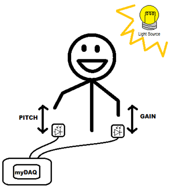
The myDAQ Optical Theremin is a musical instrument which is played in a similar method compared to a real theremin. It uses two photodiodes as optical sensors for input from the performer and generates a sine wave which is output via the headphone jack. The performer moves his or her hands over the sensors to control the intensity of light. One sensor is used to control the pitch and the other changes the gain. When the user moves his or her hands up and down over the sensor the pitch and gain raise and lower accordingly.
Materials
· 1x myDAQ
· 1x Speaker/Headphones
· 2x Photodiodes
· 2x 741 Op-Amps
· 4x 5.1Mohm resistors
· 2x Breadboards/perfboards/something to hold the circuit
· 10x pieces of wire
Estimated Cost: $5 + myDAQ + Speaker/Headphones
Software Instructions
Software for the myDAQ Optical Theremin is included in the attached zip file. Open the myDAQ Optical Theremin VI and use the Max and Min Pitch knobs to set the highest and lowest frequencies to be generated. Use the Max and Min Level sliders for Pitch and Gain to configure the amplitude range that will be seen by each sensor. The program scales the output frequency range and gain to be equally distributed across the amplitude ranges for those respective inputs.
To configure visual pitch markers select the notes your want to display in the Pitch Markers array control. To configure auto-tune select the notes you want to tune to in the AutoTune Pitches array control. Enable auto-tune with the AutoTune toggle switch.
Note: The DAQ Assistant is configured for the myDAQ unit to be named “Dev1”. If you have configured your myDAQ differently you will need to modify both DAQ Assistant VIs.
Also, the DAQ Assistant VI performing the analog output is configured by default to generate at 100kS/s and write 6.5k samples to the myDAQ at a time. Depending on the performance of your computer you may experience a buffer underflow error -200621 because the program cannot generate data fast enough for the myDAQ to maintain continuous analog output.
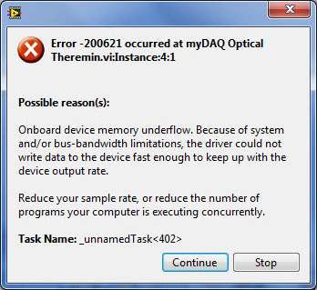
If you experience this error you will need to modify one, or both, of the following settings:
- Increase the "Samples to Write" in the second DAQ Assistant VI and increase the "Number of Samples" in the Simulate Signal Express VI. Both of these values should be the same.
- Decrease the "Rate (Hz)" in the second DAQ Assistant VI and decrease the "Samples per Second" in the Simulate Signal Express VI. Both of these values should be the same.
It will take a little bit of fiddling to figure out which settings work best with your computer. You want to have the largest sampling rate and smallest number of samples to write as possible because it will minimize the system delay from input to output.
Hardware Instructions
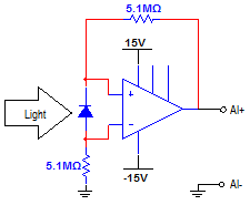
Build two instances of the photodiode amplifier circuit on either a breadboard or soldered to perfboard. Use the +15V, -15V, and GND sources on the myDAQ to power the circuit. The input for AI0- and AI1- should both be tied to ground. The output of the amplifier circuit to control pitch should be connected to AI0+ and the amplifier circuit to control gain should be connected to AI1+.
Photodiode Amplifier Circuit Diagram
Usage Diagram
Video
- Mark as Read
- Mark as New
- Bookmark
- Permalink
- Report to a Moderator
can you convert this for LV 8.6?
- Mark as Read
- Mark as New
- Bookmark
- Permalink
- Report to a Moderator
It's uploaded as myDAQ Optical Theremin LV86.zip now. Enjoy! 
Applications Engineering
National Instruments
- Mark as Read
- Mark as New
- Bookmark
- Permalink
- Report to a Moderator
The LV 8.6 zip is still a higher version than 8.6.1
- Mark as Read
- Mark as New
- Bookmark
- Permalink
- Report to a Moderator
Sorry about that. It looks like I accidentally selected LV2009 as the save version instead of LV8.6. It should be fixed now.
Applications Engineering
National Instruments
- Mark as Read
- Mark as New
- Bookmark
- Permalink
- Report to a Moderator
That works. Thank you
- Mark as Read
- Mark as New
- Bookmark
- Permalink
- Report to a Moderator
Cool!
- Mark as Read
- Mark as New
- Bookmark
- Permalink
- Report to a Moderator
not work the circuit, what is the input signal? implement the circuit and simulate out put is 14.2v this not change, what is the range in volts of the output?
- Mark as Read
- Mark as New
- Bookmark
- Permalink
- Report to a Moderator
The "input signal" is the light hitting to photodiode. If you seeing a constant output around 15V then either the ambient light is too bright or there is something wrong with the circuit. You will need to either move to a darker location or change the resistor values to work with the amount of light in your location... or better yet, make them variable!
Applications Engineering
National Instruments
