- Document History
- Subscribe to RSS Feed
- Mark as New
- Mark as Read
- Bookmark
- Subscribe
- Printer Friendly Page
- Report to a Moderator
- Subscribe to RSS Feed
- Mark as New
- Mark as Read
- Bookmark
- Subscribe
- Printer Friendly Page
- Report to a Moderator
myPOWERHELMET
Title: myPOWERHELMET
Overview of what project is:
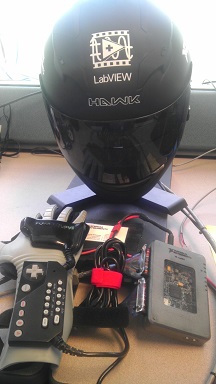
myPOWERHELMET is a Daft Punk or Deadmau5-esqe LED helmet. Using a modified Nintendo Power Glove, the user can control what is displayed on the screen by making hand gestures or pressing buttons on the glove. Depending on materials purchased, the myPOWERHELMET will cost $350-500 to build (not including the cost of a myRIO-1900 and tools). If you design your own code and hardware, this project should take one to two months to complete.
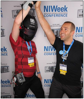
Pictures of project:
Video of project:
Parts and Materials List:
- Motorcycle Helmet
- 4.5V @ 7A voltage regulator (We used a LM27402 Demo Board)
- 0.08” Thick Clear Acrylic Sheet (3’ x 3’ sheet should be fine)
- Plywood (3’x 3’ should be plenty)
- 60 LED per meter RGB LED Strip
- 3 x Female DB9 connectors with solder cups
- 2 x Male DB9 connectors with solder cups
- 1 x Female-to-Male DB9 Right Angle Adapter
- 2 Position Male/Female Interlocking Connector (we used Radioshack P/N: 2740222)
- 1 x Rounded 3.5” Floppy Drive Cable (34 pins)
- ½” 2 hole Conduit Strap
- 11.1V 5000+ mAh Lithium Polymer Battery & Associated Connectors
- 3S Low Battery Voltage Alarm
- Barrel-shape DC Power Jack for myRIO
- Small Protoboard
- Double sided foam tape
- Assorted Heatshrink
- Zip Ties
- Nintendo Power Glove
- 3 x 100 kΩ Pull down resistors
- 4 x 500 kΩ resistors
- 3 x normally-open momentary pushbuttons
- 3’ of 24 or 26 gauge stranded copper wire. A variety of colors will help.
- 2 x 4’ of 16 gauge stranded copper wire. Each strand having a different color will help.
- 5’ of 9 wire 24 or 26 gauge cable
- Dean Plug Parallel Y-Extension (One Male, Two Female)
- 2 x Male Deans Connectors
Tools List:
- myRIO-1900 with USB cable
- Small flathead and phillips screwdriver
- Soldering iron and solder
- Heat Gun
- Wire Strippers
- Laser Cutter
- CAD software
- Scissors
- LabVIEW 2013
- Digital Multimeter
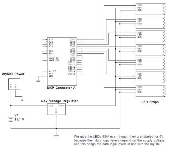
Wiring Diagram:
Power Glove: 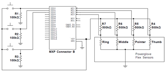
Helmet:
Instructions:
1. How WS2811 Smart Pixels Work
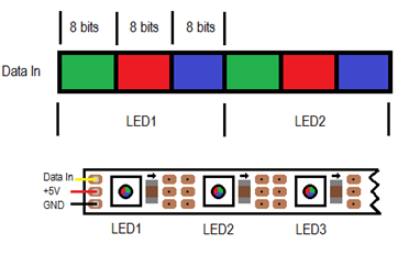
a) Before we can dive into this project, we must understand how the LED strips work. Each 1m strip is comprised of 60 “Smart Pixel” RGB LEDs, which each have an integrated WS2811 driver chip. Once this chip is commanded to set the red, green, and blue brightness for its corresponding LED, it automatically performs and maintains the appropriate PWM signal for the LED without any further commands or outside intervention.
b) Now, how do we talk to the LEDs? We set each the color of each pixel by sending it 24 bits – The first 8 bits are the green brightness, followed by 8 bits each for the red and blue brightness. Once an LED receives 24 bits of data, it starts passing through all other data it receives to the next LED down the chain. When that 2nd LED receives 24 bits of data (and so far we have sent out 48 bits of data in total), it also begins forwarding data. This continues until all LEDs in the chain have been programmed. After this, we hold the data line low for a set duration which causes all the LEDs to update and hold their new values.
c) How do we send the 1’s and 0’s for each bit? Now we must delve into the WS2811 driver chip’s datasheet! From the datasheet, we see to send the most significant bit first, and also get the following waveforms and table:
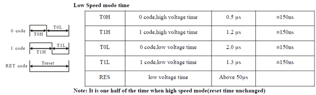
d) Armed with the above knowledge, we now know how to send all relevant data, and in what order to send it!
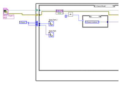
2. Explaining the Software
a) The attached project consists of three parts: A master state machine which ties everything together, a FPGA VI (Bit_Out.vi), and a set of drivers for communicating with WS2811 RGB LED strips, using the protocol detailed above.
b) The drivers read in a 7 pixel tall 24 bit bitmap image of any length. For each row, the drivers read in the red, green, and blue value of each pixel and send the corresponding “1” or “0” waveforms as an array of Booleans (True when the data should be high for 50ns, False when the data should be low for 50ns) into a Host to Target DMA FIFO. For example, if the waveform to send a “1” required the waveform to be high for 150ns and low for 50 ns, the array sent would be <T,T,T,F>.
c) Once “Output Update” is run, the FPGA VI begins iterating through the Booleans in the FIFOs. Every 50ns the FPGA VI reads a new value from the FIFO for each row, and sets the outputs accordingly.
d) A typical way to use the Vis in this driver is as follows:
Read Bitmap for LEDs --> Apply an Effect VI (optional) --> Send Image to LEDs --> Output Update
e) A fun application of the above structure is to make an animation by horizontal scrolling a bitmap image by 16 pixels at a time! The bitmap need just contain each subsequent frame of animation to the right of the previous one.
3. Modifying the Power Glove
a) The first step in modifying the Power Glove is to make use of the flex sensors. To do this we need to create a voltage divider that we can use to read the flex sensor values in the fingers. Open up the case near the fingers on the glove.
b) Remove the four Diodes that are circled in the picture below and replace each one with a 500 kΩ resistor (see Power Glove Wiring Diagram above).
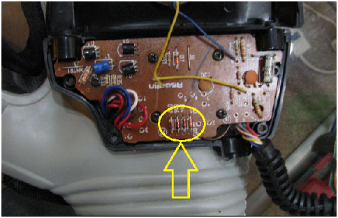
c) With the 4 resistors in place, you can use a multimeter to measure and map out which resistor corresponds to each finger (note that the pinky does not contain a flex sensor, therefore there are only four resistors in our voltage divider). With the multimeter set to measure Ohms, place the meter’s probes between the center tap of one of the voltage dividers and ground. Bend each finger until you notice a change in resistance. Continue this process for all four resistors.
d) Now open up the Power Glove case that sits above your forearm. Inside this case we will throw away the existing PCB and build our own. All that we will need from the old PCB is the bundle of wires entering and leaving the case. Snip the wires carefully off the old PCB, as you want them to be as long as possible. You will use these wires on your new PCB.
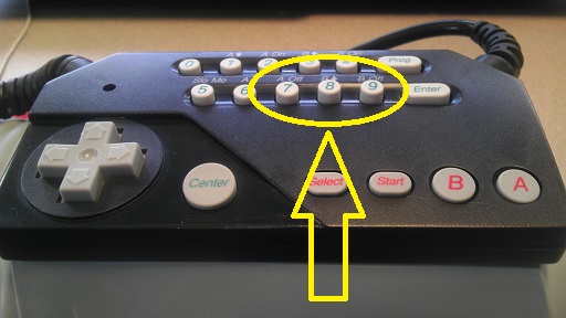
e) On the new PCB you will be adding the 3 normally-open momentary pushbuttons. You will also be adding a 100 kΩ pull down resistor for each button (see Power Glove Wiring Diagram above). Adding your own buttons can be tricky since you must make the buttons fit snug underneath the rubber pads of the Power Glove control panel. Due to the limited room inside the case and the length of the wires, we were only able to add buttons beneath pads 7, 8, and 9 on the Power Glove control panel. Experiment with different configurations, and see what works for you! Be aware that you will need to save room for a couple more wires on your PCB in the next step. The three buttons should now be wired to the pins of the Power Glove plug.
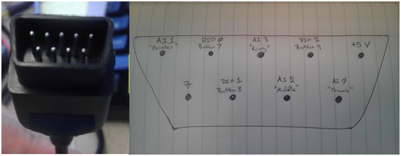
f) Now connect the four wires that are attached to the flex sensors of the glove to the bundle of wires that are leaving the case. The flex sensors should now be connected to the pins on the Power Glove plug. Below is the mapping for the plug that we made and their corresponding I/O lines for the myRIO. Again, your mapping may be different depending on how you wired your PCB.
g) Close up the two cases carefully so not to pinch any of your wires. The Power Glove should now be finished modifying!
4. Building the Helmet
a) Now that the Power Glove is finished, let’s move on to the helmet. When choosing a helmet size we went with an XL, since we knew that we would have to run wires, LEDs, and a voltage regulator inside and still have room to fit our head. We found a “Hawk” brand helmet online for about $80, and it worked perfectly. If you have the option, get a heavily shaded visor, since the LEDs will be fairly bright.
b) Our first step was to find somewhere to mount the voltage regulator. The voltage regulator is necessary because our battery is rated for 11.1V, and the LEDs required 4.5V to properly run. We removed the straps that came with the helmet, and with those gone there was a perfect cavity that our voltage regulator fit nicely in.
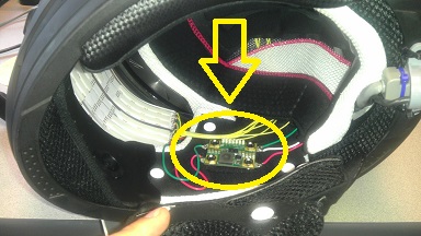
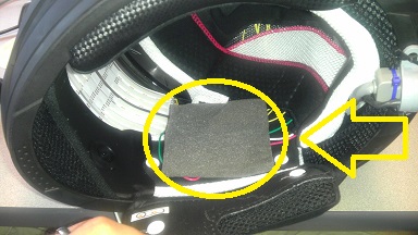
Don’t forget to insulate the voltage regulator with some Styrofoam or any nonconductive material since it will be in close proximity to your head!
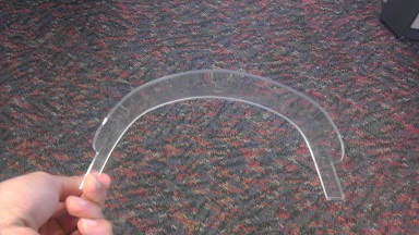
c) With our design, we wanted to make an internal clear acrylic shield that the LEDs can sit against in front of our faces. To do this we drew up the basic shape in a CAD program, cut out the design using a laser cutter, and then molded the acrylic with a heat gun against a 14” diameter circle of plywood that we also cut with the laser cutter. All of these tools were available to us at a local do-it-yourself shop that let us use their equipment.
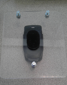
While you have access to the laser cutter and your acrylic sheet, it may be a good time to build a belt clip that can be used to connect your myRIO to your belt. Again, make a CAD drawing, and once cut, add a belt clip adaptor used on cell phones.
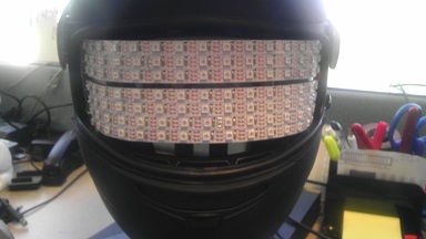
d) The LEDs were then cut into strips of 16 LEDs (this size will vary depending on your helmet, and the software must be edited to reflect your choice) and taped to the acrlic shield with double sided tape. Don’t forget to leave a slit inbetween two of the rows so that you can see out of your helmet while you wear it!
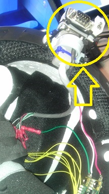
e) With the LEDs and voltage regulator in place, the next step was to run all the necessary wires. The voltage regulator and the LEDs required a power and ground, and the LEDs required 7 DIO lines (one DIO line for each row of LEDs). In the rear of the helmet we added a D-sub connector with a 90 degree adapter for two reasons: ease of connection, and they support 9 lines. We only needed 8 of the 9 lines (7 DIOs and a ground) but maybe you can find another use for the extra line!
Butted up next to the D-sub connector, we added a 2 Position Female Interlocking Connector that would connect the helmet to power and ground from the battery. Using Zip Ties and a ½” conduit strap, we were able to secure the connectors together and mounted them to the rear of the helmet.
f) All the wiring fit underneath the helmet padding. With the wiring in place, the last step was to solder the all the connections for the LEDs and voltage regulator.

5. Building the Connectors, Cables, and Dongles
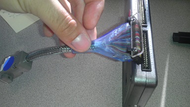
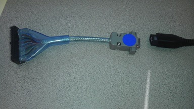
a) The last step of the project was to connect the my-RIO-1900 to the Power Glove and Helmet. To do this you will need to design a variety of dongles, connectors, and cables. Let’s start with connecting the Powerglove to the myRIO-1900.
The my-RIO MXP ports require a 34 pin connector. It turns out that Rounded 3.5” Floppy Drive Cable works perfectly for this. We cut the 34 pin connector off of the cable and added a female D-sub connector to the other end that would connect to the Power Glove’s original plug. When wiring the D-Sub, be aware of which lines you are needing from the MXP port. For our Power Glove dongle we needed to break out 4 Analog input lines, 3 DIO lines, +5V, and Ground.
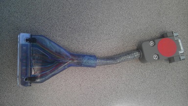
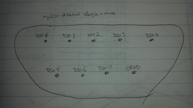
b) Next we needed to connect the helmet to the myRIO. For this we made another dongle similar to the dongle used for the Powerglove. For the helmet we needed to break out 7 DIO lines and a ground from the MXP connector.
Here is the pinout for the helmet dongle’s male pins:
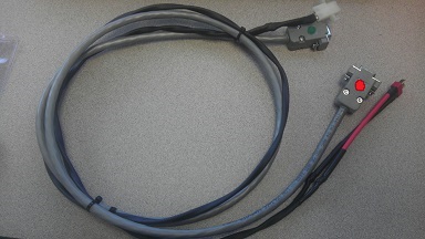
c) A cable was then made that connects the helmet to the battery and helmet dongle. The battery cable used two 16 gauge wires that could handle the current drawn by the LEDs. Note that for one end, a male Deans connector was attached to the battery, and on the helmet side, a 2 Position male Interlocking Connector was added. For the data cable we found a 9 wire, 24 gauge cable that worked fine.
d) The final connector needed is one which connects the battery to the myRIO. We connected a male Deans connector to a barrel-shape DC power jack which fits in the myRIO. Pay attention to the polarity of the power jack when wiring.
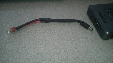
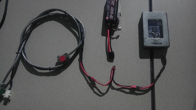
The Dean Plug Parallel Y-Extension was then used to branch out the power to the helmet and myRIO. The final configuration should look something like this:
e) Now it is time to plug everything together, install the software onto the myRIO, and let the show begin! We hope you have as much fun as we did in designing your very own PowerHelmet!
C or LV?: LV
Version of LV: 2013
- Mark as Read
- Mark as New
- Bookmark
- Permalink
- Report to a Moderator
Just fantastic.
- Mark as Read
- Mark as New
- Bookmark
- Permalink
- Report to a Moderator
Cool project.
Thanks for the heads up about the floppy disk connector. I was trying to find a pigtail connector for that MXP port and that is exactly what I needed.
