- Document History
- Subscribe to RSS Feed
- Mark as New
- Mark as Read
- Bookmark
- Subscribe
- Printer Friendly Page
- Report to a Moderator
- Subscribe to RSS Feed
- Mark as New
- Mark as Read
- Bookmark
- Subscribe
- Printer Friendly Page
- Report to a Moderator
The Bomb-Sniffing Robot
Contact Information:
University: University of Texas at Austin
Team Member(s): John Walthour, Hieu Nguyen, Lahar Gupta, and Kirtan Patel
Faculty Advisors: Travis Forbes
Email Address: jwalthour@mail.utexas.edu
Project Information
Title: The Bomb-Sniffing Robot
Description:
The Bomb-Sniffing Robot is an unmanned vehicle that uses multiple sensors to detect hazardous chemicals. This proof-of-concept design is intended to help military personnel explore harsh terrain at a safe distance, thereby reducing time, money, and lives lost.
Products:
National Instruments LabVIEW 2010
The Challenge:
The idea for developing the Bomb-Sniffing Robot originated from the fact that hundreds of men and women die each year due to undetected bombs and chemical exposure. To solve this problem, our team developed a proof-of-concept prototype called the Bomb-Sniffing Robot. Military personnel and civilian bomb squads are the target audience for the Bomb-Sniffing Robot and its design will allow them to remotely detect hazardous conditions and substances.
A successful prototype must meet operational requirements including response time, wireless range, battery life, and weight. Minimizing response time is important for this project because it allows users to have accurate and video and sensor data from the robot in real-time. The robot must achieve a response time of less than 500 milliseconds because any longer delay would be noticeable by the operator. A fast response time allows the robot to quickly navigate complex areas to find threats. When explosives or other hazardous chemicals are involved, the distance between the user and the robot is a key operational requirement of the system. Bombs can threaten lives over a large radius, so the user must control the robot from a safe distance. We feel that one hundred meters will remove the operator from the immediate blast radius and allow a sufficient area to find protective cover. The robot must operate in regions without access to reliable power sources. Providing a run-time of at least sixty minutes and allowing the batteries to be field rechargeable will provide our customers with a robot that is ready to use any time and anywhere. Robot weight is another consideration of the project. The weight of the robot and controlling laptop cannot exceed forty-eight pounds because this is the maximum weight a single soldier can carry in combat operations.
Funding is a serious constraint because asingle battlefield robot can cost $115,000, which is well beyond our group’s budget of $1,500. The lack of funds for sensitive explosive sensing electronics and the lack of access to explosives for testing dictate that this project will be a proof-of concept and not a complete solution. The robot design includes cheaper hazardous gas sensors, which detect methane and carbon monoxide, to reduce the project costs.
The Solution:
Hardware Components
The Bomb-Sniffing Robot is divided into two main subsystems: the controlling laptop and robot. As seen in the operational block diagram of Figure 1 below, each subsystem has inputs and outputs that connect over a wireless communication link.
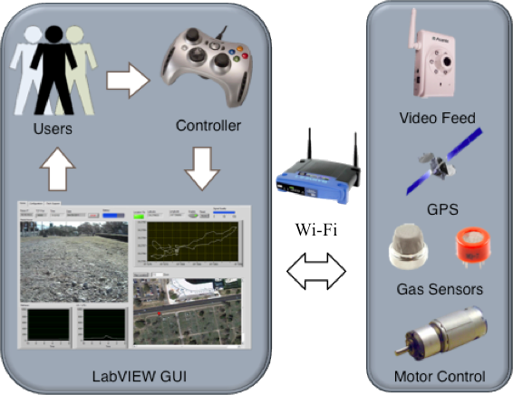
Laptop Robot
Figure 1: Operational Block Diagram
The user controls the robot and the camera using a Universal Serial Bus (USB) gamepad and views the sensor data and video stream on a GUI. The GUI collects data from the USB gamepad, formats a control message, and sends the information to the robot wirelessly. The robot then reads this message and moves the motors accordingly. The robot also collects sensor and video data from the remote environment and transmits the information back to the GUI forprocessing.
The components of the robot consist of a microcontroller, wireless router, motor controller, custom-made PCB, camera, GPS unit, DC motors, and voltage regulators. In order to identify hazardous chemicals and gases, the robot contains two different sensors to detect carbon monoxide and methane. Both of these sensors have the capability of detecting gases in the 20 Parts Per Million (PPM) to 10,000 PPM range. An onboard GPS unit provides location information to track the location of the robot and updates the location twice per second. The microcontroller and a custom PCB interface these components together, and a wireless router relays the information back to the GUI by the wireless router.
The robot’s microcontroller must interface with many different devices. The Digilent Cerebot 32MX4 was chosen because it provides enough Analog to Digital Converters (ADC), Serial Peripheral Interfaces (SPI), Pulse Width Modulation (PWM) ports, and Universal Asynchronous Receiver/Transmitter (UART) ports to interface with each of the subsystems. The ADC reads the output voltages of the carbon monoxide sensor, methane sensor, and battery voltage sensor twenty times per second and converts these output voltages into digital values that can be stored for transmission by the Ethernet controller back to the GUI. The microcontroller and Ethernet controller both use chips manufactured by Microchip and are supported by the Microchip Application Library.
A Linksys WRT54GS provides an 802.11G wireless communications link between the robot and laptop. This model operates at 12V and includes removable antennas, which make it ideal for our application. The wireless range of the router is 300 meters and exceeds the specification of a one hundred meter range. The robot also uses a Locosys 30021 GPS unit for location tracking. This particular unit was chosen because it can update ten times per second and track sixty-six channels while using a simple low voltage UART interface.
To provide live video and audio feedback from the robot, an Asante’s Voyager I network camera sits on a servo driven pan and tilt assembly. The camera operates at 12V, provides a resolution of 640 by 480 pixels, and includes Ethernet connectivity. The Lynxmotion BPT-KT Pan and Tilt allows the user to observe the environment by providing 180º by 110º field of view.
Two five amp-hour lithium-polymer batteries from Turnigy provide power to the electronics and motors separately. Switching regulators, operating at twelve volts and five volts, provide reliable power to the microcontroller, sensors, GPS unit, wireless router, and video camera. Each of these regulators protects the circuitry from over-voltage and over-current with Zener diodes and fuses. The Sabertooth 2X25 dual channel motor controller is powered directly off the second battery pack and can supply each motor with twenty-five amps of current. The team chose this motor controller because of its high power output,low cost, and simple servo-style interface for controlling the speed and direction of each motor. This motor controller also includes similar over-current and over-voltage protection mechanisms.
Two DC brushed motors work simultaneously to move the robot’s tank-like tracks, allowing the robot to traverse difficult terrain. The team chose two twelve-volt, 697ounce-inch motors for their high torque capability and an operating voltage close to the battery output voltage. The motors can rotate at 300 revolutions per minute, thus allowing the robot to travel at just over five miles per hour.
Software Components
The team used National Instruments’ LabVIEW to process the values received from the robot sensors and to create the GUI. Within our LabVIEW virtual instrument, two loops control all data flow in and out of the system. The first loop begins with the acquisition of data from a USB controller and finishes with the transmission of a TCP packet containing motor control information. The second loop begins with the reception of a TCP packet and ends with the filtered display of sensor information. The sensor information includes an embedded ActiveX control to display the video feed, an XY graph and Google Maps integration to display the robot’s GPS coordinates, and two graphs to display carbon monoxide and methane levels. A screenshot of the GUI can be found in Figure 2 below.
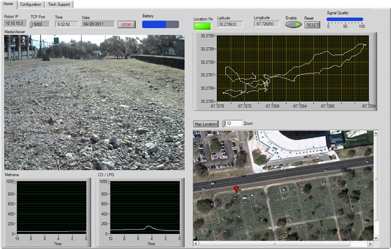
Figure 2: LabVIEW Graphical User Interface
Other features of the LabVIEW program include a tabbed interface to allow additional information, like configuration menus and technical support, to be displayed without interfering with the main functions of the program. A keep-alive routine also continually checks the status of the wireless connection. The keep-alive routine can halt the robot and prevent damage by automatically shutting down the robot if the connection is lost or becomes unresponsive.
The block diagram of the LabVIEW program is rather large and does not lend itself to being posted in this description, so please see the file attachment below that includes all of the VI's used for this project. The "Robot Control.vi" is the main VI which incorporates all the other sub-vi's.
Why LabVIEW?
Our team chose LabVIEW for the laptop GUI because it allowed very rapid prototyping and the wealth of pre-made VIs. Our project involved interfacing with USB and TCP/IP, and the time spent programming was greatly decreased by customizing the pre-made VI's for joystick data aquisition and TCP data communication rather than having to program drivers from scratch. The ability to embed ActiveX controls into the VI also allowed a seamless way to incorporate our IP camera's video stream.
A key aspect of the Bomb-Sniffing robot is its sensor array. LabVIEW provided a very simple way to add low-pass filtering and other signal processing to those sensor signals. Displaying the data is also incredible simple and only required dragging and dropping a few graphs and wires to make the GUI intuitive and user-friendly.
Photos:
Robot
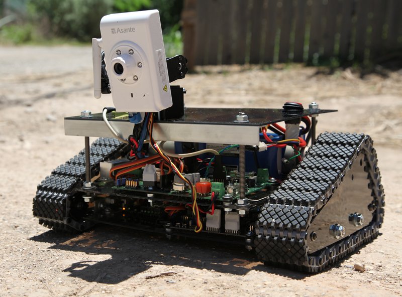
Figure 3: Bomb-Sniffing Robot
Custom PCB
Figure 4: Custom PCB designed with Advanced Circuits PCBArtist
Video Demonstration:
- Mark as Read
- Mark as New
- Bookmark
- Permalink
- Report to a Moderator
Hi jwalthour
Thank you so much for your project submission into the NI LabVIEW Student Design Competition. It's great to see your enthusiasm for NI LabVIEW! Make sure you share your project URL(https://decibel.ni.com/content/docs/DOC-16412) with your peers and faculty so you can collect votes for your project and win. Collecting the most "likes" gives you the opportunity to win cash prizes for your project submission. If you or your friends have any questions about how to go about "voting" for your project, tell them to read this brief document (https://decibel.ni.com/content/docs/DOC-16409).
I'm curious to know, what's your favorite part about using LabVIEW and how did you hear about the competition?
Good Luck, Liz in Austin, TX.
- Mark as Read
- Mark as New
- Bookmark
- Permalink
- Report to a Moderator
Looks like a fun project to work on. Very good demo video!
