From 11:00 PM CST Friday, May 9th - 3:00 PM CST Saturday, May 10th, ni.com will undergo system upgrades that may result in temporary service interruption.
We appreciate your patience as we improve our online experience.
From 11:00 PM CST Friday, May 9th - 3:00 PM CST Saturday, May 10th, ni.com will undergo system upgrades that may result in temporary service interruption.
We appreciate your patience as we improve our online experience.
Visit 2 × 2 MIMO With NI USRP for a description of this example and background information.
Hi,
I'm trying to execute this 2X2 MIMO code with 4 units of 2921.
And I'm getting errors of "A stream command was issued in the past." with Fetch API & "Packet had timestamp that was late (or too early)." with Write API.
I didn't change any parameters except IP addresses and Carrier Frequencies. (and also tried changing start trigger time)
Why does this happen?
Thanks.
Hello youngmin -
How are you syncronizing the recievers? Are you using the MIMO cable or attaching PPS and Ref In to two USRP devices?
Hi Erik,
I'm using 2 MIMO cables for Tx/Rx syncronization.
And set ref./PPS source MIMO for second USRP.
Thanks.
Hi
I want to desing 2X2 MIMO-OFDM using Labview software and USRR 2921. I have a couple of questions.
1) How many USRP 2921 can i use for 2x2 configuration?
2) Can i implement MIMO-OFDM transmitter and MIMO-OFDM receiver on the seperate two computer (transmitter on one computer and receiver on the other) ?
Thanks
Hi Erik
I m not able 2 find any reference paper for the mimo implementation using usrp wheather 2x2 or 4x4.....
and now i m stuck in the middle can you help me out...or any one can help me out of it??
Thanx...
Does this help?
http://www.ni.com/white-paper/14311/en/
Regards,
Erik
Sent from mobile device.
Hi Erik
firstly thank you 4 ur response
this is good but it is for 8x8 mimo implementation .....nd i dont have hardware for 8x8.....so pls suggest me paper for 2x2 implementation so that i can carry forward my work.....
Thanks
Hi Erik
can i add eye diagram or contellation graphs or both in the above example to view the BER in 2x2 almouti coding.....graphically..... will it work??
Thanks....
Hi Erik,
I am trying to get the 2x2 MIMO with Alamouti coding example running and have run into a problem I've not seen anywhere else on this forum. My setup is using 4 USRP-2932's. I have gps antennas attached to the primary USRPs on both the Tx and RX sides. The secondary USRP's are each connected to the respective primary with a MIMO cable. Primaries are set to INTERNAL clock and secondaries are set to MIMO clock.
The problem is I seem to get no transmit. The Tx led does flash for an instant and there's a quick blip on the spectrum analyzer, but the receive time domain data is just low amplitude noise on a low frequency sinusoid. If I jumper the USRP Tx/Rx section out in the vi it seems to decode properly and display the expected constilation diagram. Has this example been tested with 2932's and gps disciplined clocks before? What am I missing??
Thanks!
Update...
Got it working by increasing the Symbols per Packet from 2000 to 200000 so I could see where the Rx was starting relative to the Tx start. Then it was a matter of adjusting the Tx Start Trigger Time and reducing the Symbols per Packet until the Rx side was capturing all the Tx data and could trigger. Seems very sensitive to small adjustments in the Start Trigger Time.
Anyway, hope this helps the next person who can't get this to work!
Thank you for sharing the updated parameters! I expect it may be fairly
system dependent on timing. If you end up adding an AGC or adaptive
energy trigger please upload the example.
Erik
Hi Erik:
I'm using 4 usrp-2920 trying to build the system, and i succeed in the previous version ,one without the BER module.
But when i came to the latest version, an error occurs all the time.It says:error -21865 occurs at 2x2QAMAlamouti with BER.vi -> niDMT.lvlib:MT Map QAM Symbols to Bits.vi:1.Possible reasons:Invalid input symbol array; Input symbol array is empty.
I've testified the system and It seems that the TX can transmit signals but the RX cannot receive anything at all. I believe that there could be something wrong with the synchronization of the TX and RX.
I can't figure out why the previous version could run properly but the new one couldn't work at all.
Is there any difference with the link of the devices?Have u ever meet the same problem? Could u give me some advice?
Should I use the extenal clock to synchronize the Tx with the Rx?It seems to be the only possible reason.
Kind regards
Hello everyone,
Could I see a working 2x2 mimo setup with the correct parameters??
Thank you guys!! 
Sincerely,
James
hi ,i want to implement adaptive channel estimation algo (not fixed algo).so can you suggest me some method so that i can start in a right way.
kind regards,
sam
hello everyone,
I am trying to run this 2x2 mimo with USRP 2920. I am also working with LabView 2014 and the USRP version 14.0 driver. When pinging my transceivers over the switch from PC everythings works fine.
The problem I have right now, is that my two transmitters do not start transmitting. LED A does not light up and so, of course, I got the message after running the VI: Input symbol array is empty.
Normally the VI should work with the new update also, or might this be the problem?
Kind regards,
Paul
I met the same error..
2x2QAMAlamouti with BER.vi -> niDMT.lvlib:MT Map QAM Symbols to Bits.vi:1.Possible reasons:Invalid input symbol array; Input symbol array is empty.
Have you resolve your error ??
> niDMT.lvlib:MT Map QAM Symbols to Bits.vi:1.Possible reasons:Invalid input symbol array; Input symbol array is empty.
hi ,have you met the error ( It says:error -21865 occurs at 2x2QAMAlamouti with BER.vi -> niDMT.lvlib:MT Map QAM Symbols to Bits.vi:1.Possible reasons:Invalid input symbol array; Input symbol array is empty. ) ?
probably happens only in new version ...
I am having similar problems. Is there anyone here who has actually run this code on the newer version and it still works? I am using 4 USRP 2921 boards. The guys from Labview do not seem to repsond to these problems in the commetnts above..
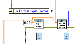
I ran into a similar issue and it seems like the trim waveform VI is taking too many samples out so that there aren't enough left by the time you reach the QAM VIs. I got the code working by just skipping that function all together:
In general energy detection is often based on a threshold set by the user. Setting the threshold too high can cause too few signals to get through, while a threshold set too low can cause noise to create false triggers. Often it is necessary to manually adjust the threshold (or write a dynamic energy detector that uses multiple past points, such as a moving average)
Hi, I want to ask in the document it says 'The code in the middle lower portion of the diagram initiates the Tx/Rx operations with the NI USRP hardware'. Does it initilize the operation only once or it repeats everytime the Tx is not triggered? If it does repeat, how can I change the system to initilize only once?
Thank you.
Hi,
I have one basic Question!, Can I ues this files by Labview Communication, or it is just for Labview?, Thanks
Hi Arash,
We are working on updating our examples into LabVIEW Communications. We will be moving some documents as necessary into new locations to support both versions. You can access a LabVIEW Communications version here https://decibel.ni.com/content/docs/DOC-42025
According your diagram,
@ErikL: I need PPN and REF in. Can i not use the internal clock and LO ?
@Peter_W : I still cant have it running even after bypassing that trim block, the output doesnt seem to change with this move. What do u think can be the problem in this case.
Hi SDR team
I've tried to sync two USRP-RIOs by exporting ref clock and pps signal from one device to another, modifying the ver.10 codes. The returned BER indicates it seems to be a successful test, however some points needed to be clarified
1. For this version of code, enable the freqency offset correct button seems to fail the test
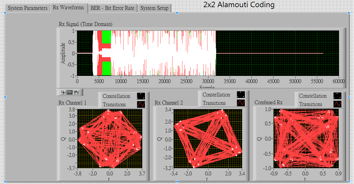
2. The BER shows 0, however the combined Rx seems not a perfect 4-QAM
3. Why MT map bits to PSK symbols is used in this QAM modulation scenario? Is there a reason for that?
4. As far as I'm concerned, this example do insert the training sequence, but it's only capable of dealing with the fractional CFO, thus for the Integer CFO caused by the LO mismatched, ref. clock is necessary for Tx/Rx synchronnization. Then how come we need not to do so in the packet transmission example in the community. Is that because in that case we additionally insert some zeros and guard interval to form a more complete packet so the ICFO wouldn't we a problem? Because I once tested this example using 4 USRPs without offering ref. clock to Tx/Rx end but it still works. So I am curious in what occasion should we have that configuration?
https://decibel.ni.com/content/docs/DOC-18801#comment-29719
Thanks!
Hi I want to calculate Channel Capacity...How can it be done..? thanks
I believe that example uses Alamouti on the Tx side and MRC on the Rx.
Let's say the signal to noise ratio over a lossless path for each Rx channel is SNR_1 and SNR_2.
You have 4 paths between the Tx and Rx
h_11 (Tx1 to Rx1)
h_12 (Tx2 to Rx1)
h_21 (Tx1 to Rx2)
h_22 (Tx2 to Rx2)
Alamouti results in the averaging of the SNRs in each path to the Rx antenna.
So you have a channel to Rx1 with SNR that is the average of the h_11 and h_12 paths.
Call this
SNR_1_Alamouti = ((|h_11|^2 + |h_12|^2)/2) * SNR_1
You have another channel to Rx2 with SNR that is the average of h_21 and h_22 paths
Call this
SNR_2_Alamouti = ((|h_21|^2 + |h_22|^2)/2) * SNR_2
MRC means that the overall SNR is the sum of all the branch SNRs. So the total SNR is
SNR = SNR_1_Alamouti + SNR_2_Alamouti
Technically, the channel capacity is
C = .5 log2 (1 + SNR)
Or C = B log2 (1+SNR) (B = bandwidth, in this case SNR includes total noise over the band)
Now, if you are asking about the actual throughput in your application, that depends on your actual channels, your bandwidth, the payload size of your packets, coding, etc. etc.
Thank u fr the information. This will ease the problem.
Hi,
For implementation of 2x2 MIMO system using USRP-2922 is it necessary to give external clock using OCXO(oven controlled oscillator) based Thunderbolt® GPS Disciplined clock from Trimble which supplies a 10-MHz Ref Clock output and digital PPS output. Or is it possible by using Function Generator as external clock pulse.
please reply.
hola estoy tratando de implementar un sistema MIMO 4x4 basado en el ejemplo de 2x2 y desearia saber si alguien puede ayudarme xfa
good afternoon Ing. Erick.
we are students of Electronic Engineering at the University Politecnica Salesiana in Ecuador , please could help us to implement a MIMO 4x4 system because we are basing your work on MIMO 2x2 and we have some questions that we can not solve .
hello,
I want to implement energy efficiency for this 2x2 MIMO system could you please suggest me how can i start with it.
An errorless VI for anyone met across the same issue as I did.
It was my graduation project 3 years ago. I solved this issue and graduated successfully. Here is my VI which can run without error. Hope it can help.
hello
how should i implement 2*2 MIMO using Poalr Coding
can anybody tell me,how to implement 2*2 mimo with polar coding in labview with USRP RIO 2943
Hello,
The 2*2 MIMO I set up uses the USRP-2920. When I run the above program, I follow the set clock source written on the white paper. The address is only changed elsewhere. However, it was reported that "niUSRP Fetch Rx Data (2D CDB).viERRA stream command was issued in the past.". I did not find a solution after reading all the comments. Is there any solution? Where did the problem occur? Is it necessary to match an external clock source? Also, if there is no solution, can you share the code of the earliest version of this article? Because I saw the previous comment that the original code was not wrong. Thank you! I hope someone can help me.
best wishes
Hello
I am trying to implement this example on a single device——ettus B210 which have 2 TXs and 2 RXs. I have completed the single antenna transmission example on it.
I'm faced with a problem I don't know how to solve——I changed the parameters like fllows:

IP address of Tx settings(192.168.10.2;192.168.10.3) and Rx settings(192.168.10.4;192.168.10.5) are changed to device name(myb210);
The active antenna is changed to TX1、TX2、 RX1、RX2 of per device (actually only the B210);
The Frequency source and clock source are changed to Inter.
Also, in 'subAsyncMuliti-ChannelTransceiver.vi', I changed the channel list of 'niUSRP set time.vi' from '0' to '0,1' (there's no MIMO cable, so I think that every channel should be set).
However, when i runned the example, it was reported that the error 'niUSRP Write Tx Data (2D CDB).vi<ERR>Packet had timestamp that was late (or too early).'
How should I solve it? Further, is it possible to implement 2x2MIMO on a single USRP?


