- Subscribe to RSS Feed
- Mark Topic as New
- Mark Topic as Read
- Float this Topic for Current User
- Bookmark
- Subscribe
- Mute
- Printer Friendly Page
Labview -> Arduino Mega (1280) -> Pololu VNH3SP30 Motor Driver -> 2Pumps
09-25-2012 06:33 AM
- Mark as New
- Bookmark
- Subscribe
- Mute
- Subscribe to RSS Feed
- Permalink
- Report to a Moderator
Hi there,
I got some issues wile using a Pololu VNH3SP30 Dual Motor driver with Labview. I allready posted my problesms along with all the informations here:
http://forum.pololu.com/viewtopic.php?f=15&t=5912&p=28104#p28104
I tried to interface the Motors directly through the Arduino and did not had an alternating fluid flow as I was experiencing when using LIFA.
do you guys have an suggestions what I might have done wrong when programing the Motor control program in LabView?
Any sugestions are highly appreciated.
Thanks a lot.
Best regards,
Jan
09-25-2012 05:33 PM
- Mark as New
- Bookmark
- Subscribe
- Mute
- Subscribe to RSS Feed
- Permalink
- Report to a Moderator
Hi Folks,
well I just wanted to show you my setup. Here is a short Youtube video:
http://www.youtube.com/watch?v=w6ByllD4W6k&feature=g-upl
And here is a snapshot of my LabView Program.
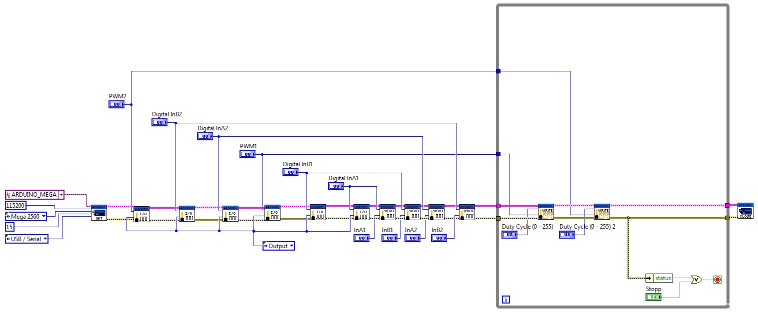
Do you guys see any reason why I get an alternating motor behavior when using LIFA? The same Program flashed via the Arduino IDE 1.0 works fine.
It must be something about the PWM timing in the while loop but I can't figure it out.
Best regards,
Jan
09-25-2012 09:04 PM
- Mark as New
- Bookmark
- Subscribe
- Mute
- Subscribe to RSS Feed
- Permalink
- Report to a Moderator
I didn't read everything but you may need to consider the frequency of the PWM because the maximum for your device is 10kHz.
09-26-2012 03:20 AM
- Mark as New
- Bookmark
- Subscribe
- Mute
- Subscribe to RSS Feed
- Permalink
- Report to a Moderator
Hi Nathan,
what exactly is it you suggest? To change the PWM frequency? In my understanding the Arduino uses somwhat of 900 Hz as default. With a 16MHz crystal installed on the board one is able to change PWM frequency to somewhat around 30kHz. I guess I can change that in the LIFA_base.pde for the Arduino. Right?
But what I do not understand is the fact the the setup works for 1 motor. If PWM frequency should be to slow than that should allready be the case with the first motor. But I'm experiencing problems only then when i switch on the second motor.
What exactly do you think I should do?
Best redgards,
Jan
09-26-2012 05:38 AM
- Mark as New
- Bookmark
- Subscribe
- Mute
- Subscribe to RSS Feed
- Permalink
- Report to a Moderator
Hi there,
I just figured out that the following Code works perfectly when flashed directly onto the Arduino MEGA using the Arduino 1.0 IDE:
| int InA1 = 22; | |
| int InB1 = 23; | |
| int PWM1 = 8; //PWM1 connects to pin 8 | |
| int PWM1_val = 127; //(25% = 64; 50% = 127; 75% = 191; 100% = 255) | |
| int InA2 = 24; | |
| int InB2 = 25; | |
| int PWM2 = 11; //PWM1 connects to pin 11 | |
| int PWM2_val = 127; //(25% = 64; 50% = 127; 75% = 191; 100% = 255) |
| void setup() { | |
| Serial.begin(9600); | |
| pinMode(InA1, OUTPUT); | |
| pinMode(InB1, OUTPUT); | |
| pinMode(PWM1, OUTPUT); | |
| pinMode(InA2, OUTPUT); | |
| pinMode(InB2, OUTPUT); | |
| pinMode(PWM2, OUTPUT); | |
| digitalWrite(InA1, LOW); | |
| digitalWrite(InB1, HIGH); | |
| digitalWrite(InA2, LOW); | |
| digitalWrite(InB2, HIGH); | |
| } |
| void loop() { | |
| analogWrite(PWM1, PWM1_val); | |
| analogWrite(PWM2, PWM2_val); | |
| } |
Now what I do not understand is why a LabView Program which mimics the exact code as given above does not work. Not working in the sense that I still have an unsteady Flow when both pumps are turned on.
Just wanted to share my thoughts.
Best regards,
Jan
09-26-2012 11:15 AM
- Mark as New
- Bookmark
- Subscribe
- Mute
- Subscribe to RSS Feed
- Permalink
- Report to a Moderator
Hi there,
i now used an oscilloscope to take a look at the PWM outputs directly from the Arduino MEGA. Meaning that the Driver board was not connected.
Using the above given LabView Program I got the following result:
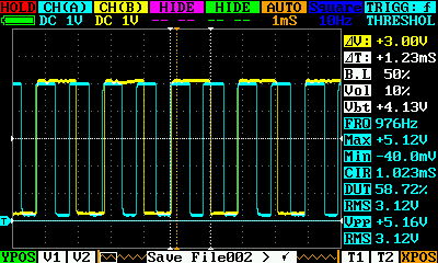
Both PWM Channels were set to the exact sam Duty Cycle - But it is clearly visible that the blue channel is twice as fast as the yellow one. Why is that?
Now, using the same "code" (see my previous post) flashed via the ARDUINO IDE 1.0 directly onto the board, I got these results:
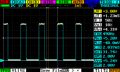
As one can see both PWM Channels are perfectly aligned - as one would suspect.
Anyone got any idea why using two PWM outputs via LIFA is so messed up?
Best regards,
Jan
09-26-2012 01:29 PM
- Mark as New
- Bookmark
- Subscribe
- Mute
- Subscribe to RSS Feed
- Permalink
- Report to a Moderator
Hello together,
I found the solution! Somewhere on the forum someone wrote that LIFA only supports Pins 3,5 and 6 for PWM output. As I recall it this was due to the fact that the "serialWrite" command is used. Unfortunatly I lost the thread so I can not link it. However, when I changed my PWM-Pins to 3 and 5 everything worked as it shoud. It seems that even when the Arduino Mega support up to 13 PWM Pins these are not fully exploitable via the LIFA Toolkit. Maybe taht will change in the future, but until now, the only way to use multiple PWM Pins seems to be to stick to the Pins 3,5 and 6!
I attached my working VI for future reference. This VI is capable of driving 2 DC Motors via an Dual Motor Driver such as the Dual VNH3SP30 Motor Driver Carrier MD03A (http://www.pololu.com/catalog/product/707/specs) from Pololu.
Hope this will be helpful to someone someday.
Best regards,
Jan
