- Subscribe to RSS Feed
- Mark Topic as New
- Mark Topic as Read
- Float this Topic for Current User
- Bookmark
- Subscribe
- Mute
- Printer Friendly Page
Tutorial Presentation: FPGA-based Real-Time Simulation of Power Electronics: Challenges & Solutions
01-04-2012 06:42 PM
- Mark as New
- Bookmark
- Subscribe
- Mute
- Subscribe to RSS Feed
- Permalink
- Report to a Moderator
This is a new presentation containing background information and tips and tricks for overcoming the challenges of developing real-time hardware-in-the-loop (HIL) simulations for switchmode power electronics systems. The presentation begins with background information on the National Instruments vision for power electronics and an overview of new products and tools in development. The next section introduces real-time HIL simulation and explains why it is a necessary practice for high quality, high reliability product design. Processor based simulation is examined and compared to the newer FPGA-based approach. Then a summary of FPGA-based real-time simulation challenges and solutions is presented, with detailed technical information and tips and tricks for overcoming each challenge. A link to the new 3-Phase Inverter RCP and HIL Reference Design and training videos is given. The presentation concludes with an overview of finite element analysis (FEA) based simulation in LabVIEW FPGA, based on a collaboration with JSOL Corporation and the JMAG-RT electromagnetic simulation tools.
PRESENTATION TOPICS:
- BACKGROUND- NI VISION FOR POWER ELECTRONICS
- BACKGROUND- REAL-TIME HIL SIMULATION OF POWER ELECTRONICS
- PROCESSOR BASED SIMULATION
- FPGA SIMULATION CHALLENGES & SOLUTIONS
- STATE-SPACE BASED FPGA SIMULATION
- FEA MODEL BASED FPGA SIMULATION
01-04-2012 06:45 PM
- Mark as New
- Bookmark
- Subscribe
- Mute
- Subscribe to RSS Feed
- Permalink
- Report to a Moderator
If anyone is interested in a narrated version of this slide deck, please reply to this thread and let me know.
01-05-2012 04:53 AM
- Mark as New
- Bookmark
- Subscribe
- Mute
- Subscribe to RSS Feed
- Permalink
- Report to a Moderator
Great work!!
Great to learn about so many possibilities of implementing an Inverter HIL!! I am surely interested in a narrated version of the work! Also, I have few queries on the same, which I hope would add more essence to the blog post.
Firstly, to give a background of my relation with this work,We are working on developing a Inverter-Motor-Engine HIL for evaluating Engine ECU and motor controller and motor simulataneously.We have tasted a little success in implementing an Engine HIL with the help of this forum.Now, we are in a process of realizing an Inverter-motor HIL.
I have already tried the same on a DSP, but I've failed to achieve low sampling rates ( 1Mhz as req by the inverter). So, we have shifted focus onto porting inverter model onto an FPGA!
My queries are:
1. How accurate is the fixed-poind mathematical model of the Inverter mentioned in the 3-phase inverter RCP and HIL ref. design. We are already in the process of evaluating it, but it would be resourceful if you can comment on it. By accurate I mean: How near is to a practical Inverter?
2. Is it possible to run the inverter model by creating a custom device, similar to the engine model (this).
3. Is going to FPGA, the ultimate solution for realizing an Inverter ( or any switched mode power elec. ckt). Can't we realize the same on a RT controller, using Interrupts?
Looking forward to a resourceful discussion.
Thanks
Vijay.
01-12-2012 11:54 AM
- Mark as New
- Bookmark
- Subscribe
- Mute
- Subscribe to RSS Feed
- Permalink
- Report to a Moderator
Hi Vijay!
Thanks for your note. Great comments- I apologize for being so slow to reply. The new year has been a whirlwind. I hope it's a good sign of an improving economy.
Regarding FPGA versus DSP, I think there is growing consensus in the industry that FPGA-based real-time simulation is the technological winner. Even with high end processors or GPUs, bus latency typically puts a hard speed limit at about 10 us (100 kHz). In theory, DSPs could be faster (than processors) assuming no bus between the processing cores and I/O, but it can be a challenge. True parallelism of an FPGA and the fast pin-to-pin times are unbeatable. It feels to me like industry consensus is converging on FPGAs as the solution, and the DSP core counts are going up with Moore's Law, which, because of it's exponential nature, becomes increasingly impactful in the next few years. (The rate of MMAC performance improvement is proportional to the MMAC performance itself.) However, harnessing the parallel processing capabilies of large FPGAs is a real challenge using text based programming languages. LabVIEW is a more natural model of computation since it's always embraced the concept of multiple, parallel tasks executing in parallel. So, LabVIEW maps beautifully to FPGAs, arguably more naturally than it maps to processors (at least single core ones).
Regarding your queries...
1. The accuracy of the fixed point model can be very high. It really depends on how you map to the fixed point word lengths, which depends on the component values you have (max and min R,L,C for example) and how you do the matrix scaling/normalization. To get a feel for this, run the VI in the reference design titled "Verify Fixed Point Matrix Normalization Scaling." Pick some scaling values (Vo, Io), then click "Run Sim". At the end of the simulation, you will have three error values representing the difference between the floating point simulation results and the fixed point (FPGA) simulation. You will see that different scaling values will impact the amount of fixed point error.
I am working on updating this example to improve the way the matrix normalization scaling is done. This will give you three scaling parameters to use and enable you to scale every value in the state-space matrix. I also made a version of the state-space for the case in which the load inductance is zero. If you set Lload=0, it uses the alternative flavor of the A matrix. I still have some work to do in cleaning this up and documenting how the normalization scaling is done, but if anyone needs this sooner rather than later, I can post it as is, and then finish cleaning it up later.
2. Yes, you can absolutely integrate this into Veristand by creating a custom device. However, keep in mind that the communication with Veristand is typically single-point rather than waveforms, so you may need an alternative communication mechanism such as LabVIEW Simple Messaging (STM) to stream the waveforms from the Multicore cRIO or PXIe RT system to the host computer. I'll ask our Veristand gurus to comment on this.
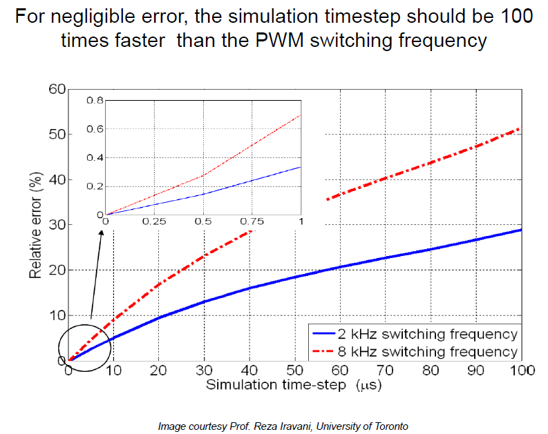
3. Yes, FPGA is really the ultimate solution, with clear technical advantages in terms of speed over a processor. Yesterday I updated the PDF with a chart from Prof. Iravani that shows the simulation accuracy for a 2 kHz and 8 kHz PWM switching carrier frequency on the inverter relative to the simulation speed. In the updated PDF, this is slide 46. On a processor based simulator, you typically start to hit a real wall at around a 10 uS. The problem is not so much the speed of the processor but the latencies involved, responding to the interrupts, transfering data back and forth, memory read/writes/queuing, etc. For an 8 kHz inverter, that's about 9% error, which is really significant. You really want sub-microsecond rates for your real-time simulator, which FPGAs can easily provide.