InvenSense MPU 6050 GY-521
- Subscribe to RSS Feed
- Mark as New
- Mark as Read
- Bookmark
- Subscribe
- Printer Friendly Page
- Report to a Moderator
Code and Documents
Attachment
Overview
I bought an MPU 6050 6DOF (Degrees of Freedom) it has 3 accelerometers and 3 gyro sensors. I had an Arduino Uno and set about programming the Arduino to read the sensor values, once I had the raw values I wanted to pass them through a complentry filter and a Kalman filter. I wrote some additional code on the Arduino to implement the two filters. I was able to see the values for pitch,roll and yaw in my terminal Software putty, but this was not very meaningful seeing just numbers. I wanted to have a graphical representaion of what was happening. So I used a 3D picture control in LabVIEW and was able to stream the values from the MPU into LabVIEW via serial. I also wanted to be able to see the different data components, Raw Data, Complimentry Filter data and Kalman Filter data.
Description
The MPU 6050 communicates with the Arduino over I2C. The .ino included with this commnity example sets up the I2C communication with the Arduino.
Wire Connection diagram
Uno MPU6050
AI 4 SDA
AI 5 SCL
5V VCC
GND GND
Mega MPU6050
SDA (Pin 20) SDA
SCL (Pin 21) SCL
5V VCC
GND GND
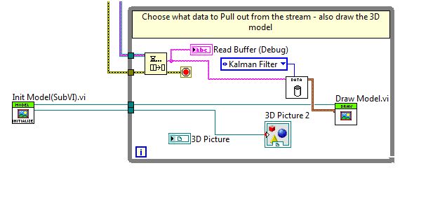
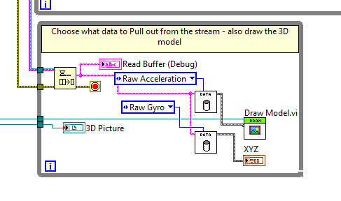
What the VI does is gives a 3D picture control that models the moevment of the MPU. There are subVI's in the project that can pull out the Raw gyro data, complementry filter data and the kalman filter data.
Steps to Implement or Execute code
1. Install Arduino programming Enviroment (1.0.5 or later)
http://arduino.cc/en/Main/Software
2. Upload Arduino Code (.ino) to Arduino Uno or Arduino Mega.
3. Run the LabVIEW VI
4. Move the MPU and observe the movement on the 3D picture control.
To modify the code to read other values, such as the Raw, Complementry or Kalman Data I have created Sub VIs that will be able to give that information.
Requirements
Software
Arduino Programming Enviroment (1.0.5 or Later)
LabVIEW 2012 or Later
Hardware
Arduino Uno R3
or
Arduino Mega 2560
MPU 6050 GY-521
Applications Engineer
National Instruments UK&Ireland
Example code from the Example Code Exchange in the NI Community is licensed with the MIT license.
- Mark as Read
- Mark as New
- Bookmark
- Permalink
- Report to a Moderator
great work!!!
- Mark as Read
- Mark as New
- Bookmark
- Permalink
- Report to a Moderator
Hello
Thanks for posting your VI and arduino code.
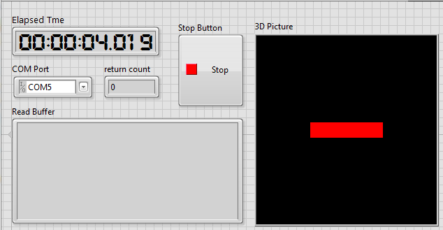
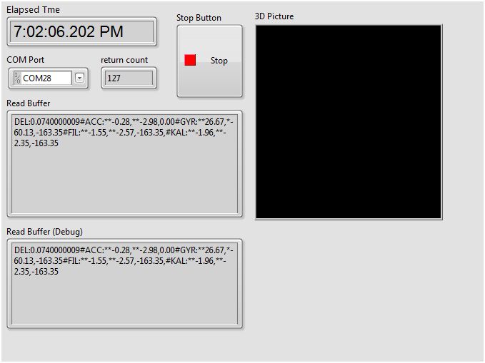
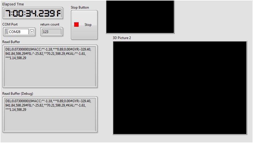
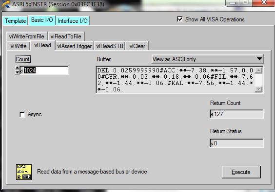
I can not see the 3D shape on screen but I am reading buffer from VISA read.
Would you please take a look at my screenshot ? and tell me if I am getting a correct reading from Arduino board ?
I am using Arduino Mega 2650, Windows Vista, and LabVIew 2012
The read buffer is someting like this:
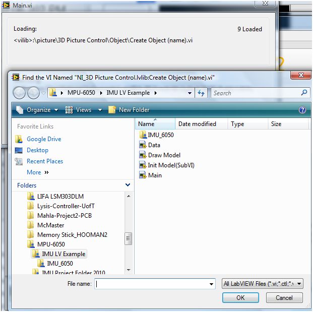
There is file missing when I was going to run "Main" vi in "IMU Project Folder 2010" folder ? is this the reason ? how can I obtain that vi ?
Regards,
Hooman
- Mark as Read
- Mark as New
- Bookmark
- Permalink
- Report to a Moderator
Hi Hooman,
I am glad you have downloaded my code. Are you using LabVIEW full? or base?
Please take a look at this KB it may help to ensure you have openGL graphics card
http://digital.ni.com/public.nsf/allkb/65AF800249870B3B862577BB003AEF83?OpenDocument
Let me know how you get on
Applications Engineer
National Instruments UK&Ireland
- Mark as Read
- Mark as New
- Bookmark
- Permalink
- Report to a Moderator
Hello
I have downloaded the OpenGL view ... I can see the 3D image. I went to NI example finder and found a VI called " solarsystem.vi " there is 3D image in that VI and I was able to control it. So i think 3D graphic is working fine.
I am using a full verion of LabVIEW 2012,
Please advise.
Regards,
Hooman
- Mark as Read
- Mark as New
- Bookmark
- Permalink
- Report to a Moderator
Hooman,
Thanks for your reply. Is the code now working for you?
Kind Regards
Applications Engineer
National Instruments UK&Ireland
- Mark as Read
- Mark as New
- Bookmark
- Permalink
- Report to a Moderator
Hello
no it is not working for me yet.
How can I trouble shoot this?
thanks,
Hooman
- Mark as Read
- Mark as New
- Bookmark
- Permalink
- Report to a Moderator
Hi Hooman,
A trouble shooting step for you. Delete the 3D picture control that I have placed down, and try and place down another one. The 3D picture control can be located in Modern pallette> Graph >> 3D Picture.
Wire it up and let me know how you get on.
I look forward to hearing from you.
Kind Regards
Applications Engineer
National Instruments UK&Ireland
- Mark as Read
- Mark as New
- Bookmark
- Permalink
- Report to a Moderator
Hello
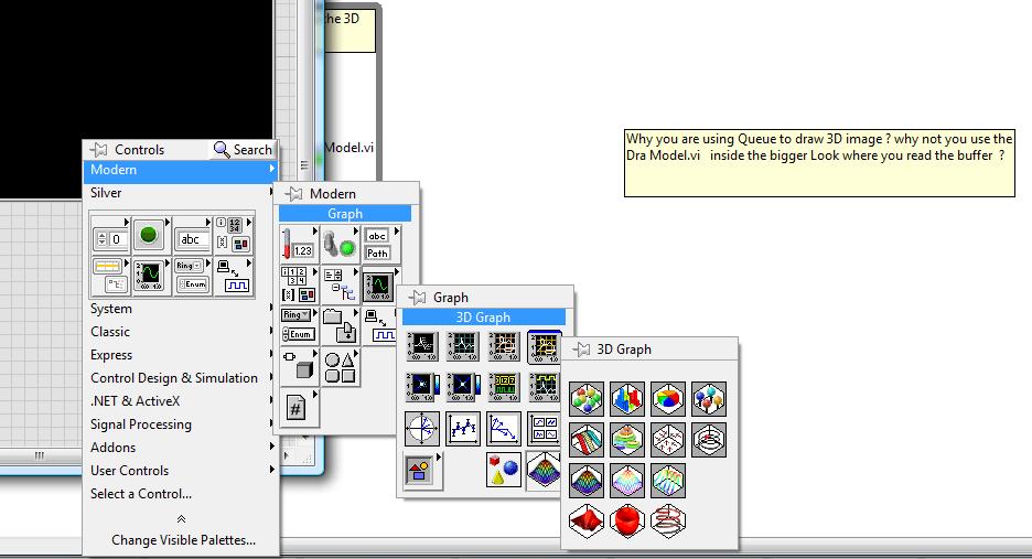
I don't have the " 3D Picture ".
what should I do?
Thanks a lot for your help.
Hooman
- Mark as Read
- Mark as New
- Bookmark
- Permalink
- Report to a Moderator
Hi Hooman,
You do have it, you are looking in the 3D Grpah pallette. Just to the left of that you will the 3D picture control.
3D Picture control install with LabVIEW it is something that is native.
Let me know how you get on.
Kind Regards
Applications Engineer
National Instruments UK&Ireland
- Mark as Read
- Mark as New
- Bookmark
- Permalink
- Report to a Moderator
Hi
I used it but no picture yet!
pelase see the screen shot .
- Mark as Read
- Mark as New
- Bookmark
- Permalink
- Report to a Moderator
Hi hooman,
It looks like there could be something wrong with youur LabVIEW please do a repair on the LabVIEW enviroment and see if that remedys the problem
Kind Regards
Applications Engineer
National Instruments UK&Ireland
- Mark as Read
- Mark as New
- Bookmark
- Permalink
- Report to a Moderator
Hello
I have repaired the LabView and now everything is working fine. Thanks a lot for your help...
now, I want to add one more MPU sensor to this. How do you think I can achive this ?
Regards,
Hooman
- Mark as Read
- Mark as New
- Bookmark
- Permalink
- Report to a Moderator
Hi Hooman,
That is great news, I am glad you are able to use my code.
I terms of using a second IMU, I have provided the code for one, you can extrapolate the idea and expand it for a second IMU.
Good Luck
Kind Regards
Applications Engineer
National Instruments UK&Ireland
- Mark as Read
- Mark as New
- Bookmark
- Permalink
- Report to a Moderator
Hi
The sensor is on my desk and I am not moving it but the 3D image is keep rotating on x y plane ? while it is rotating the 3D image shakes ? Do you know what is causing this? hwo can I fix this bug ?
Thanks,
Hooman
- Mark as Read
- Mark as New
- Bookmark
- Permalink
- Report to a Moderator
Sure.. I will add it and I will put my code..
Thanks again for your help.
Hooman
- Mark as Read
- Mark as New
- Bookmark
- Permalink
- Report to a Moderator
hello i m also using your code but 3d pic is rotating itself and i am not moving my sensor but it giving fluctuations and rolling?
- Mark as Read
- Mark as New
- Bookmark
- Permalink
- Report to a Moderator
Hi ram17yadav,
It sounds lik your sensor is at fault here. Please have a look at the raw data in a terminal program, or use the built in serial viewer in Arduino IDE. If you see fluctuation there it will be the sensor not the LabVIEW code. Please take a look at your wiring.
What Arduino board are you using?
Kind Regards
Applications Engineer
National Instruments UK&Ireland
- Mark as Read
- Mark as New
- Bookmark
- Permalink
- Report to a Moderator
All who have commented and I have helped please comment and give kudos
Many thanks
Applications Engineer
National Instruments UK&Ireland
- Mark as Read
- Mark as New
- Bookmark
- Permalink
- Report to a Moderator
Hello Kev_R
Thanks for the help... I am currently working to fix the bug and attache the second MPU sensor ... I will update my code if this works ...
what do you mean by " kudos " ? do mean to click on the "like" ?
thanks,
Hooman
- Mark as Read
- Mark as New
- Bookmark
- Permalink
- Report to a Moderator
So I want to use the Mpu-6050 (with an Arduino uno) on a quadcoper, and I know(at least I think I do) that the board needs to be tethered to a computer in order to run the processing sketch. Is there a way to untether the Arduino from the computer so it could be used in a quadcopter?
- Mark as Read
- Mark as New
- Bookmark
- Permalink
- Report to a Moderator
I am not familar with processing, I have herd of it but I have never used it. I use LabVIEW for my graphical interface, hence this example. However if you want to use an arduino unthethered, you can look at a bluetooth link.
Check out my blog for more information:
http://krprojects.wordpress.com/my-quadcopter/
Applications Engineer
National Instruments UK&Ireland
- Mark as Read
- Mark as New
- Bookmark
- Permalink
- Report to a Moderator
Hey Kev,
Thanks for posting this great program! I just have one question for you: Is it possible to simulatenously output both the gyroscope and accelerometer data with your VI? I've been trying to alter it to be able to do this but I'm having a little difficulty understanding how to accomplish this goal. Ideally, I'd like to be able to output both as seperate waveform charts (which I have currently working with the gyro -- just not the accelerometer.) but even knowing where to get the raw data would suffice.
Any insights would be greatly appreciated
- Mark as Read
- Mark as New
- Bookmark
- Permalink
- Report to a Moderator
Hi Kev,
I am currently trying to use your program. I have followed all the insturctions except for the fact that I have an arduino mini pro instead of an uno (the uno and mini pro have the same pin layout). I beleive my problem lies with my Visa serial communication. I am using bluetooth, and have succesfully connected it. In the putty I use is streams the data nicely using your arduino code you provided. When I try the labview however, I keep recieveing this error. Property Node (arg 1) in VISA Configure Serial Port (Serial Instr).vi. Attached here are some screenshots that show my attempted serial configuration, as well as proving that NI was correctly reading the data via COM5. Note that the baud rate for the mini is 115200.
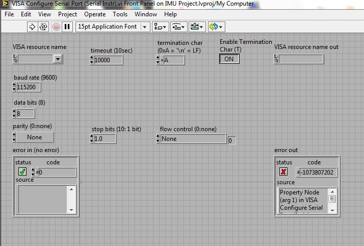
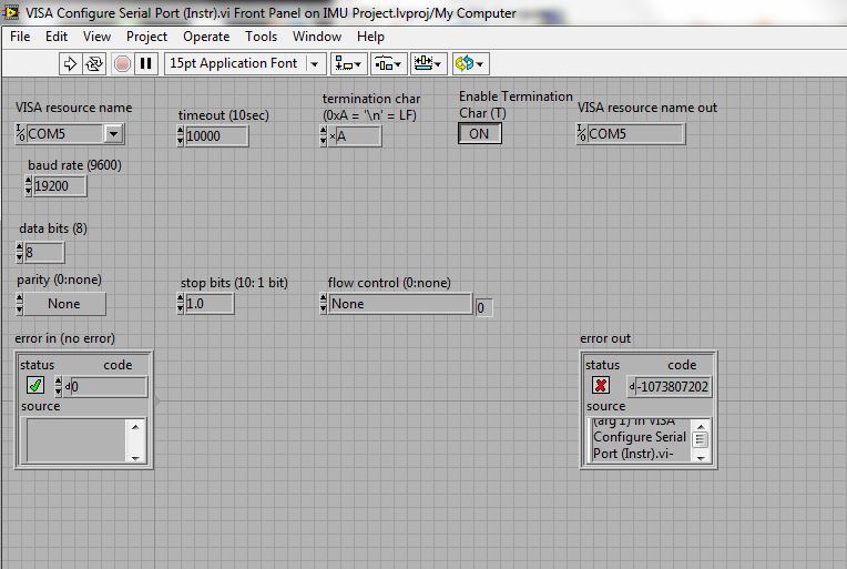
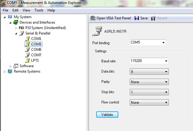
I'd just like to be able to use the program you provided with the adruino mino pro and bluetooth. Any advice would be appreciated.
Best,
Fellow engineer.
- Mark as Read
- Mark as New
- Bookmark
- Permalink
- Report to a Moderator
Hey mkeese,
Thanks for downloading my code. Yes it is possible to similtaneouly read the gyro and te accelerometer. In the bottom loop there is a SubVI called data. You will need to make a copy of this VI and wire it the the Read Buffer(Debug) coming out of the queue. Change the Enum constant to be what you want
Applications Engineer
National Instruments UK&Ireland
- Mark as Read
- Mark as New
- Bookmark
- Permalink
- Report to a Moderator
Hi mumbusta
Please ensure that you have closed putty and the MAX when tryign it in LabVIEW.
Also what version of LabVIEW are you using and what Version of the NI VISA driver are you running.
Many Thanks
Applications Engineer
National Instruments UK&Ireland
- Mark as Read
- Mark as New
- Bookmark
- Permalink
- Report to a Moderator
I was sure to close both prior to using Labview. I am using the most recent version of the NI Visa driver (just downloaded it yesterday) and am also using Labview 2012 Full version. Any other tips you might have to troubleshoot?
Thank you
- Mark as Read
- Mark as New
- Bookmark
- Permalink
- Report to a Moderator
Hello Kev_R
I don't know how to thank you for your help..... if you send me your address I will send you a gift for appreciation ( for real).
anyway.
I am trying to connect 2 of GY-521 and represent it in 3D. With one sensor works great.
here what I have done:
Sensor1: Sensor's 1 power to Arduino Board (Mega 2560) Ground and 3.3v. SCL and SDA of sensor connected to SCL and SDA of Ardiono Board. ( No modification to board)
One sensor works fine.
Sensor 2: Soldered AD0 to VCC , and connect the same way as sensor one.
I have increased buffer size to 800 on Main Vi but I have read nothing on the buffer .
Can you advise ?
thanks for any comments.
- Mark as Read
- Mark as New
- Bookmark
- Permalink
- Report to a Moderator
Hey Kev what are the dfifferneces between the IMU Project Folder 2010.zip and the IMU Project.zip?
Does it matter which one you use?
Also could you tell me how to convert the Raw Acceleration Values? I plotted the total magnitude of the XYZ directions' respective RAW Acceleration values and would now like to plot them in m/s^2 if possible to measure the initial acceleration of a rotating shaft.
Thanks for any comments.
- Mark as Read
- Mark as New
- Bookmark
- Permalink
- Report to a Moderator
Thanks a lot............you saved my day 
- Mark as Read
- Mark as New
- Bookmark
- Permalink
- Report to a Moderator
Thanks for your vi's and work. It's not as accurate as I wish it was but it really helped me with MIU 9150 which I'm working on now. Thank you
- Mark as Read
- Mark as New
- Bookmark
- Permalink
- Report to a Moderator
hi
i need help
i follow all the steps
the connection is good
but it does not work the 3d object is rotating
just like someone commented above.
what is the solution please?
- Mark as Read
- Mark as New
- Bookmark
- Permalink
- Report to a Moderator
me funciono perfectamente, para los que tengan el mismo problema estoy usando el mpu6050 de sparkfun, se debe conectar el pin vio a los 3,3v
arduino uno o arduino nano
VDD 3,3V
GND GND
AI4 SDA
AI5 SCL
VIO 3,3V
- Mark as Read
- Mark as New
- Bookmark
- Permalink
- Report to a Moderator
Hi, Thanks for the great works. Is it possible to use this code and VI with 2 MPU6050 in 1 arduino uno?
- Mark as Read
- Mark as New
- Bookmark
- Permalink
- Report to a Moderator
HI Kev_R
THANK YOU FOR SHARING YOUR LIBRARY
i have used your library for my project and everything works fine , but there is a minor problem and I dont understand it at all. while I'm rotating the mpu6050 to +90 or -90 the kalman filter and complementary filter give high accurate data but while i rotate the the IMU to +180 or 360 degrees , the box does not rotate and it gets back to 0 degree.
I have three brand new mpu6050 and i have tried all but I have received same result with all of them.
I appreciate if you help me out.
- Mark as Read
- Mark as New
- Bookmark
- Permalink
- Report to a Moderator
hola a todos:
que debeia hacer para poder controlar unos motores con este programa?
- Mark as Read
- Mark as New
- Bookmark
- Permalink
- Report to a Moderator
very good
you are genius!!!
- Mark as Read
- Mark as New
- Bookmark
- Permalink
- Report to a Moderator
I have a question concerning your project . After a while the sensor readings are not accurate. Specifically for the y axis . Do you know what the problem is ?
Many thanks
- Mark as Read
- Mark as New
- Bookmark
- Permalink
- Report to a Moderator
I hava the same problem bro, any idea? i just started to work with the sensor
- Mark as Read
- Mark as New
- Bookmark
- Permalink
- Report to a Moderator
any one know about IMU mpu 6050 gy 25 with serial communication ?
- Mark as Read
- Mark as New
- Bookmark
- Permalink
- Report to a Moderator
Hey Kev,
Your program is really great and will help me with the rest of my study project. But there is one thing I can't do: recover the read data in the read buffer at the same speed and with the same precision as they fit into the front panel.
Did I make myself clear?
Thank you for your help and great work.
