- Subscribe to RSS Feed
- Mark Topic as New
- Mark Topic as Read
- Float this Topic for Current User
- Bookmark
- Subscribe
- Mute
- Printer Friendly Page
Arduino-Labview Communication with DAC6573
Solved!07-01-2013 12:22 PM
- Mark as New
- Bookmark
- Subscribe
- Mute
- Subscribe to RSS Feed
- Permalink
- Report to a Moderator
Hey,
I would like to ask for your advice. I'm right now working on a project of mine. I would like to drive the breakdown voltage of a diode. This voltage is a value between 68V and 74V. I use an Arduino Uno with Labview Interface. Within the Labview I have the chance to adjust a value between 0 and 2.5V. I use a I2C Bus so the data goes via the SDA to the digital to analog converter in order to transform the digital value in an analog voltage. Right after, the voltage goes to the ADL5317 - which amplifies the value by a fixed value of 30.
At the moment I would like to tell the DAC to transfer a voltage such as 2.5V (in binary) and return the analog voltage. I'm a beginner to the Arduino as well as the Labview. Therefore I went through many example vi's etc. but I keep having trouble with my vi (see attachement). At the vi I first initiate the Arduino as well as the I2C Bus. Right after I go for a write function to tell the Arduino the control byte (which channel and mode) and the data word (I attached the Datasheet of the DAC6573).
Control Byte=00010000
Data Word=0000000001 (for 2.5V by 5V Reference)
Address: 1001100 (without 0 or 1) as I think the read/write information is already fixed by the vi.
After I have done this I do a read out to get the result of the conversion. What happens when I start the programm is that I see the L Led - so the code is uploading. Right after I see the TX Led one time flashing and after the RX Led flashing for about4 minutes. But the indicator does not show any value. I tried already many things but I do not get it work.
Do you guys know why it does not function?
I would really appreciate your help, as I already work for a while on that problem.
Thank you!
Christian
Solved! Go to Solution.
07-01-2013 07:44 PM
- Mark as New
- Bookmark
- Subscribe
- Mute
- Subscribe to RSS Feed
- Permalink
- Report to a Moderator
First thing is first. When you run a VI using LIFA, no code is uploaded to the Arduino. The firmware must be uploaded to the Arduino via the Arduino IDE. If this has been done already, next thing is to make sure that you are successfully communicating with the Arduino.
If the Blink VI is successful, then you are ready to start working with your device. I've looked over the datasheet for the DAC6573 for a couple hours and have come up with several modifications to your code. The VI is attached. I've based the writing and reading on pages 19 and 22, respectively.
07-02-2013 05:31 PM
- Mark as New
- Bookmark
- Subscribe
- Mute
- Subscribe to RSS Feed
- Permalink
- Report to a Moderator
Hi Nathan,
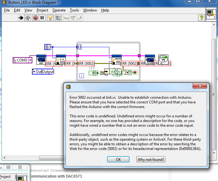
First of all thank you a lot for the work you put in to help me. The modification you have done to the VI are very helpfull. I tried the whole day fixing another problem I came accross while running the modified code. I always thought the problem why the RX LED is flashing constantly is the code but it seems to be the Init.vi which causes the problem. I was running the code and turned on the tracking mode. The loop runs just fine but as soon as the init.vi is reached it takes a very long time to proceed to the next vi (i2c init) and the RX LED ist constantly flashing (TX just flashed 2 times and then turns off for the rest of the code). When the first and only read.vi is reached the fist error occurs - Error 5003/2 - which means that the connection to the Arduino is lost. Before that I got another Error 1073807246. As its a case structure it repeats all the write and the one read.vi till I hit the stop button. After the first error occured at the read.vi it repeats and it shows all the time a read/write.vi is passed an Error (5002/03).
Anyways I was focused the day on Error 5003/2 and the init.vi. I looked through a lot of forums etc. and this issue seems to be a common one. Many guys try to increase the timeout of there Arduino to 100000 but that does not work for me. So I had a look at the baudrate - I shifted between 9600 and 115200 and made sure the Arduino, MAX and Windows Baudrate is the same. Still no success. I came accross a different approach of RyanNaz who deleted the Flow Control Part but again no success. I doublechecked my installed Software. I reinstalled the most recent NI-VISA, VI Package Manager as well as the LIFA 2.2..0.79.
Other than that, I removed the USB Cable switched port as well as Laptops but no success. The strange thing is, that I used the Arduino for a different project and I had the same results - Error 5002/3 but when I ran the Code on another PC (didnt had the chance to run the actual code on it yet) no Error at all occurred.
I looked around all day but I can not figure out, why it does not function. Somehow I believe it is something very simple (like a missing driver) but I can not think of it.
Do you have an idea? Once again your help is very welcome and appreciate!
Thank you again & good wishes,
Christian
07-02-2013 10:53 PM
- Mark as New
- Bookmark
- Subscribe
- Mute
- Subscribe to RSS Feed
- Permalink
- Report to a Moderator
Try this. Upload the original unmodified LIFA firmware to the Arduino. Then, run this VI as-is and see if you are able to turn on the LED when you hold down the button. If you get error 5002, add a constant to the "VISA Resource" terminal and select the same "COM" port that you chose when you uploaded the code with the Arduino IDE. Let me know what happens.
07-03-2013 06:09 PM
- Mark as New
- Bookmark
- Subscribe
- Mute
- Subscribe to RSS Feed
- Permalink
- Report to a Moderator
Hello,
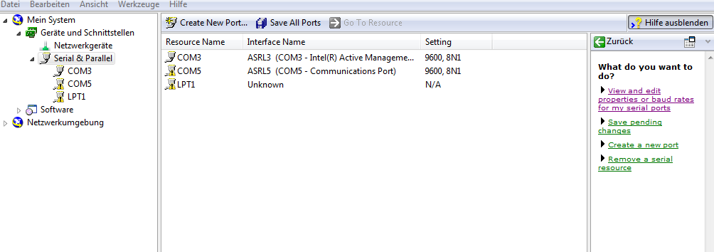
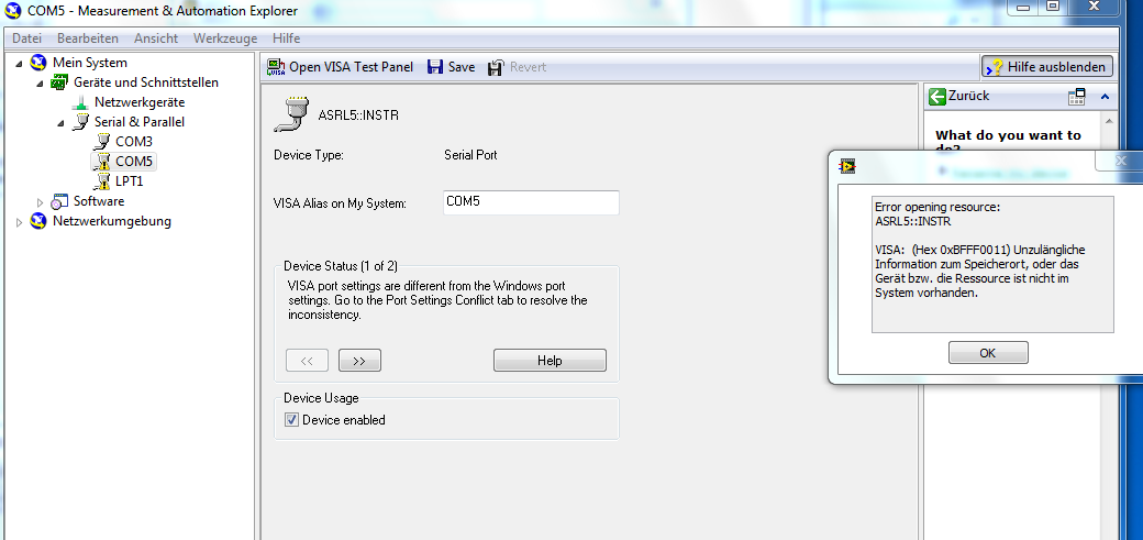
Once again thank you for your support. This morning I tried your code but it did not work. But I got another PCB/ Labview Project I used to see if my entire Setup on the PCB etc. is working. So I tried it and unfortunately I encouterd the same probelms as I had with the DAC. I thought about it and I came up with the idea to remove the pull up resistors as the Atmega has already internal ones. After I removed them, the other projects was just working well without any erros. So I moved back to the DAC one but unfortunately I still keep having the erros. I tried your code also and had the 5002/5003 errors. I could not choose the right port - Com5 - I unplugged it etc. no success. I checked in the MAX and I have a caution sign next to the port alltough the windows device manager says everything is fine. I will attach some pictures. The warning at the Error3.png on the right side says: The information to the storage place is not accessible or the ressource is not in the system.
Do you have any idea how to get this fixed?
Thanks Nathan!
Christian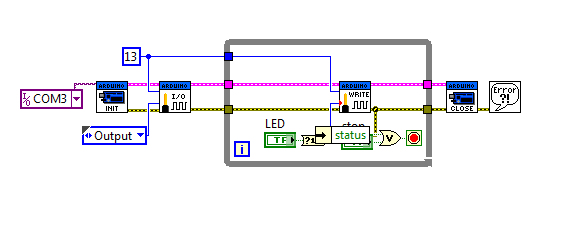
07-03-2013 07:06 PM
- Mark as New
- Bookmark
- Subscribe
- Mute
- Subscribe to RSS Feed
- Permalink
- Report to a Moderator
I'm really confused now. You are using COM3 in your code but COM3 is not a valid port based on your screenshots of MAX (I've never used MAX when using Arduino or ChipKIT, always used the Windows Device Manager). What shows up in your Windows Device Manager? If you have not since fixed the issue, could you post a screenshot of your device manager with both the "Other Devices" and "Ports (COM & LPT)" sections open and if there happens to be somewhere else that actually shows the Arduino?
What port do you use when you upload the firmware to the Arduino with the Arduino IDE (arduino.exe)?
07-11-2013 08:25 AM
- Mark as New
- Bookmark
- Subscribe
- Mute
- Subscribe to RSS Feed
- Permalink
- Report to a Moderator
Hello Nathan,
sorry for taking so long to reply. I has some problem on the harware side - I had to integrate an SDA, SCL Repeater. Now the signal look like the way they should. Also the port issues etc. are fixed. Anyways I'm still not able to receive any results. I do not get the voltage in Labview and also I'm not able to measure a voltage on one of the output pins of the DAC.
The write functions works properly - I can clearly see the 0,1's but the read functions does either not work (error 5003) or (in most case) simply returns a 0. Should I have done changes in the firmware (base.pde?).
Here are once again my ytes:
Address Byte: 1001100
Control Byte: 00010000
MSB Byte: 10000000
LSB Byte: 00000000
so if it worked fine it would show the value 2.5V (5V Reference). But as I said no voltage on the output pins. Do you might have an idea what the error / Problem could be?
Thanks Nathan!
Christian
07-11-2013 03:28 PM
- Mark as New
- Bookmark
- Subscribe
- Mute
- Subscribe to RSS Feed
- Permalink
- Report to a Moderator
The way that you have your VI written does not conform to the datasheet for writting data to the device. Both bytes must be sent in a single write operation. I made a small mistake in my previous VI but I have uploaded a fixed version with a better description of what the input data is.
When using my VI, you simply put the value of the 10-bit data in the control. So, if you want to write a 10-bit value of 214 (0b0011010110) you put 214 in the "10-bit Input Data" control. The VI will convert it appropriately to conform to the datasheet specifications.
I can't really tell what value you are trying to input based on your last post (it's different than what you said in your first post). Your first post says you want to write a value of 1 and your latest post says you want to write a value of 32768 (which is not possible with only 10-bits).
