- Subscribe to RSS Feed
- Mark Topic as New
- Mark Topic as Read
- Float this Topic for Current User
- Bookmark
- Subscribe
- Mute
- Printer Friendly Page
Communication between Arduino Uno and SPI device
07-10-2014 04:32 PM
- Mark as New
- Bookmark
- Subscribe
- Mute
- Subscribe to RSS Feed
- Permalink
- Report to a Moderator
Hello everyone!
I am using a SPI DAC (MAX 5312) to get a voltage between -/+10V. My code with the Arduino Software works when I send a binary code to the DAC input.
Now I'm trying to use Labview. I didn't get any respond on the DAC output when I was using my Labview program. So I connected the Arduino MISO Pin to the DAC input (connected to the MOSI Pin) to see if the code I was sending was correctly transferred.
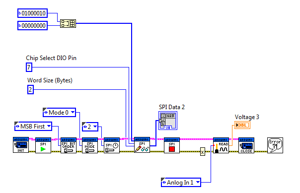
Please see on my enclosed front panel file what happens when I try to send a binary code to the DAC (SPI Sata Sent).
The SPI Data 2 is the data I'm receving on the MISO Pin.
I just put a voltage indicator to see if Labview and my Arduino board were well connected and they are.
I've must have done something wrong but I really can't find it.
Here are my labview program and my front panel during the execution.
Thank you.
07-10-2014 05:39 PM
- Mark as New
- Bookmark
- Subscribe
- Mute
- Subscribe to RSS Feed
- Permalink
- Report to a Moderator
If you could post your working Arduino code (the code that you said works when not using LIFA) then it will be easier to figure out what might be wrong.
07-14-2014 01:20 PM
- Mark as New
- Bookmark
- Subscribe
- Mute
- Subscribe to RSS Feed
- Permalink
- Report to a Moderator
Ok here is my working Arduino code :
#include <SPI.h>
// SPI Pins
const int csPin = 7;
const int mosiPin = 11;
const int misoPin = 12;
const int sclkPin = 13;
// Initialize SPI
void setup() {
pinMode(sclkPin,OUTPUT);
pinMode(10,OUTPUT);
pinMode(mosiPin,OUTPUT);
pinMode(csPin,OUTPUT);
pinMode(misoPin,INPUT);
digitalWrite(csPin, HIGH);
SPI.begin();
SPI.setBitOrder(MSBFIRST);
SPI.setDataMode(SPI_MODE0);
SPI.setClockDivider(SPI_CLOCK_DIV2);
}
// Datas transfer
void loop() {
int commandPlusData = 0b0100001000000000;
digitalWrite (csPin, LOW);
SPI.transfer (highByte (commandPlusData));
SPI.transfer (lowByte (commandPlusData));
digitalWrite (csPin, HIGH);
}
07-14-2014 09:47 PM
- Mark as New
- Bookmark
- Subscribe
- Mute
- Subscribe to RSS Feed
- Permalink
- Report to a Moderator
The only thing that I see wrong is the data you are sending the device. According to your front panel image you are sending the following bits:
0b0000000000000001000000000000000000000001000000010000000000000000000000000000000000000000000000000000000000000000000000100000001
According to the Arduino code, you want to send:
0b0100001000000000
This translates to two bytes: 66 and 0. These are the who numbers you should send to the device in the "SPI Data Sent" array.
You can do it in either decimal or binary display by changing the display format of the constant/control/indicator.
04-30-2017 05:28 AM - edited 04-30-2017 05:46 AM
- Mark as New
- Bookmark
- Subscribe
- Mute
- Subscribe to RSS Feed
- Permalink
- Report to a Moderator
I want to control the voltage of a digital potentiometer with arduino. I have found the program of MCP41010 with arduino software (IDE). As I know the first thing is we include the SPI.h library.
I want to write the program with labview. how can i do it?
04-30-2017 05:31 AM
- Mark as New
- Bookmark
- Subscribe
- Mute
- Subscribe to RSS Feed
- Permalink
- Report to a Moderator
This is the program in IDE:
/*MCP41010 Tutorial*/
#include <SPI.h>
const int CS = 10;
int PotWiperVoltage = 1;
int RawVoltage = 0;
float Voltage = 0;
void setup() {
pinMode (CS, OUTPUT);
Serial.begin(9600);
SPI.begin();
}
void loop() {
// move the potentiometer in one direction
for (int level = 0; level < 255; level++)
{
MCP41010Write(level);
delay(100);
RawVoltage = analogRead(PotWiperVoltage);
Voltage = (RawVoltage * 5.0 )/ 1024.0;
Serial.print("Level = " );
Serial.print(level);
Serial.print("\t Voltage = ");
Serial.println(Voltage,3);
}
delay(2000); // wait a couple seconds
// Now mover potentiometer in other directions
for (int level = 255; level > 0; level--)
{
MCP41010Write(level);
delay(100);
RawVoltage = analogRead(PotWiperVoltage);
Voltage = (RawVoltage * 5.0 )/ 1024.0;
Serial.print("Level = " );
Serial.print(level);
Serial.print("\t Voltage = ");
Serial.println(Voltage,3);
}
delay(2000);
}
void MCP41010Write(byte value)
{
// Note that the integer vale passed to this subroutine
// is cast to a byte
digitalWrite(CS,LOW);
SPI.transfer(B00010001); // This tells the chip to set the pot
SPI.transfer(value); // This tells it the pot position
digitalWrite(CS,HIGH);
}
05-15-2017 09:16 PM
- Mark as New
- Bookmark
- Subscribe
- Mute
- Subscribe to RSS Feed
- Permalink
- Report to a Moderator
I would recommend one of three approaches:
- Use LINX with the native SPI functionality from LabVIEW
- Use LINX with a custom command that calls Arduino code (this approach allows you to reuse some of your existing Arduino code and will likely be the easiest)
- Create your own custom communication with the Arduino using basic serial communication in LabVIEW. (This approach is likely the hardest)
