- Subscribe to RSS Feed
- Mark Topic as New
- Mark Topic as Read
- Float this Topic for Current User
- Bookmark
- Subscribe
- Mute
- Printer Friendly Page
Firmware of AC dimmer
05-01-2014 04:17 AM
- Mark as New
- Bookmark
- Subscribe
- Mute
- Subscribe to RSS Feed
- Permalink
- Report to a Moderator
hey guy
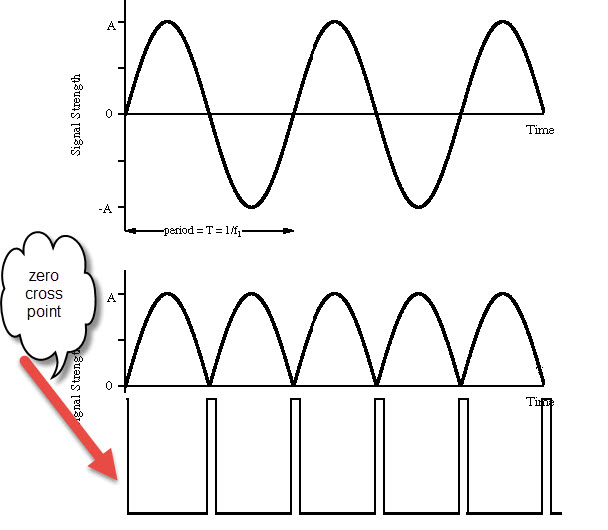
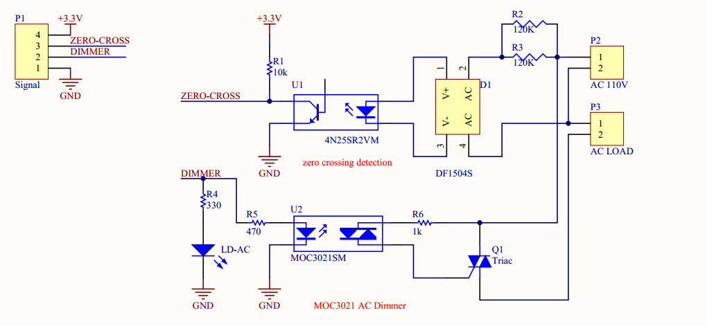
i want catch rise edage of signal(as shown in figure 1) come from zero cross point circuit (as shown in figure 2).
the zero cross point catch from pins accroding to
the flowing Interrrupt table
Pin | Interrrupt # | Arduino Platform
---------------------------------------
2 | 0 | All
3 | 1 | All
18 | 5 | Arduino Mega Only
19 | 4 | Arduino Mega Only
20 | 3 | Arduino Mega Only
21 | 2 | Arduino Mega Only
and do processing than output signal to any output digital pins((note: program for this processing i put it in attach Files))
please,i want anyone have a knowledgement for editing Firmware help me
i made editing Firmware and i put also in attach Files
but i have problem in fuction of Interrrupt
Thanks
05-01-2014 05:11 AM
- Mark as New
- Bookmark
- Subscribe
- Mute
- Subscribe to RSS Feed
- Permalink
- Report to a Moderator
I don't understand what you are asking for. It's not possible to use the interrupts directly in LabVIEW. Also, please use .zip files when uploading archives.
05-01-2014 07:36 AM
- Mark as New
- Bookmark
- Subscribe
- Mute
- Subscribe to RSS Feed
- Permalink
- Report to a Moderator
thanks Mr. Nathan_B for response
i know ,It's not possible to use the interrupts directly in LabVIEW.
in my project, i want control the speed of AC fans or adjuestment time of lights to
the AC dimmer circuit is used for this purpose
this video shown how dimmer circuit work
https://www.youtube.com/watch?v=WMErMdEr5aA
https://www.youtube.com/watch?v=QdvGmm-vvW8
i will send from LabVIEW number of digital pin and dimming(_PWM) paramerter to aduino( adjuestment the width of high and low pluse signal)
my problem in Firmware
i changed attach Files to .zip format
Thanks
05-01-2014 01:15 PM
- Mark as New
- Bookmark
- Subscribe
- Mute
- Subscribe to RSS Feed
- Permalink
- Report to a Moderator
Code is available on the Internet for using Arduino to create an AC phase control Triac power controller. see:
<http://playground.arduino.cc/Main/ACPhaseControl> and
<http://www.instructables.com/id/Arduino-controlled-light-dimmer-The-circuit/>
The code uses an interrupt to start a timer at each zero crossing of the AC power waveform.
The code then compares a set point with the timer generated delay to trigger a Triac.
The code mentioned above is not compatible with the present version of LIFA. As it will take considerable time to modify LIFA to use the code mentioned above I suggest you just use Labview for sending a set point to Arduino.
hrh1818
05-02-2014 05:24 AM
- Mark as New
- Bookmark
- Subscribe
- Mute
- Subscribe to RSS Feed
- Permalink
- Report to a Moderator
thanks Mr. hrh1818
you mean i cannot using attachInterrupt(0,zeroCrossingInterrupt, RISING) in LIFA
and i ask how can do AC dimmer compatible with LIFA
please , help me or give me clear idea if u could
thank you again
05-02-2014 07:40 PM
- Mark as New
- Bookmark
- Subscribe
- Mute
- Subscribe to RSS Feed
- Permalink
- Report to a Moderator
You need to modify LIFA to get LIFA to work with your dimmer code. Start with studying LabviewInterface.imo to see how the select case structure is used to select different LIFA functions. You will need to add a case for your dimmer function. Next study Labview Interface for Arduino Packets found under the Documents tab to see how commands are sent from Labvirew to Arduino. Next study existing LIFA examples to see how packets are created. You will need to create a custom VI for use with your dimmer code. Next look at the LIFA Quadrature Encoder example Nathan created. This example will show you how Nathan modified the standard version of LIFA for use with Quadrature Encoders.
hrh1818
